The prodigious pendulum clock
Do
you know how a pendulum clock works? Do you know why mechanical clocks tick?
This is a great opportunity to learn about some remarkable machines,
with fascinating insights into mechanical engineering. Here is a  movie of the sort of clock you will build if you undertake this project. After building it, you might go on to analyse its performance in terms of timekeeping and
efficiency, and then, perhaps, improve on the design.
This type of clock
is very accurate but a little difficult to construct and fine tune. For
a simpler alternative, see the
  magnificent modular clock.
| Some annotated photographs | |
|---|---|
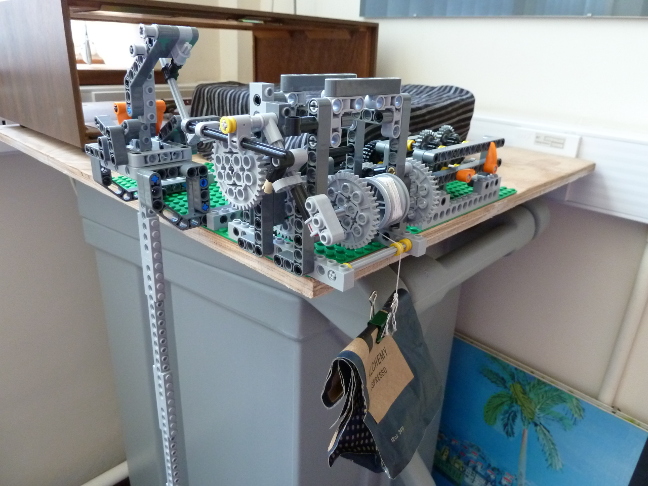 | The clock comprises three modules. At the left is the pendulum, which sits on a knife-edge suspension in a cradle. It is the beating heart of the clock. The assumption is that it oscillates at a steady rate, in this case with a period of 1.5 seconds. To measure time, all we have to do is count oscillations of the pendulum. For example, after 40 oscillations we know that a minute has passed. In the middle is the gear train and escapement mechanism. Its job is twofold. Firstly, it transfers energy from the falling weight (the coffee bag, which has a few pebbles inside it) to the pendulum, ensuring that the pendulum keeps oscillating despite the energy losses due to friction and air resistance. Secondly, it advances the escape wheel (the large 40-tooth gear at the centre of the module) by 1/40th of a revolution for every oscillation of the pendulum. The escape wheel therefore rotates once per minute. Finally, on the right, is a gearbox that is driven by the escape wheel. There is a 60:1 speed reduction between the escape wheel and the axle carrying the first orange hand, which therefore rotates once every hour. So this is the clock's minute hand. There is a further 12:1 speed reduction from the first orange hand to the second orange hand, which is the clock's hour hand. |
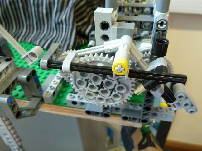 |
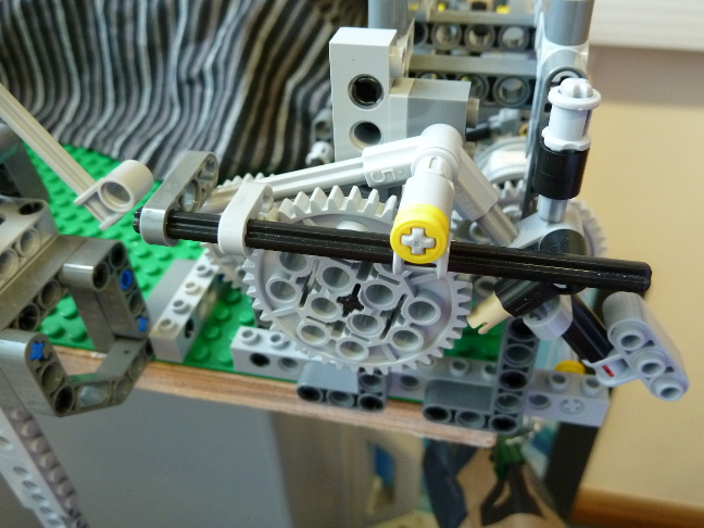
Study carefully this photo of the escapement mechanism and also this
 movie of the escapement in action. The first thing to understand is that the escape wheel is connected, through a series of gears, to the drum carrying the falling weight (the coffee bag). The weight applies a torque to the drum, which in turn applies a torque to the escape wheel, which wants to turn anticlockwise. The reason it doesn't spin freely is that it is locked by the small, light grey pallet that is wedged between two of the escape wheel's teeth at around 10 o'clock. This is the escapement in its "locked" state. But then the pendulum comes along and unlocks it. It pushes down on the light grey, inverted V-shaped gravity arm that is hanging from the axle above the escape wheel. The beige pin is knocked off the tooth it was sitting on, and the gravity arm starts to rotate clockwise, driven by the gravitational moment of the small weight (the light grey piece with the three circular pins) attached to its rightmost extremity. The left end of the gravity arm collides with the larger, dark grey pallet, lifting it up and also lifting the black axle on which it is mounted. This lifts the smaller, light grey pallet, unlocking the escape wheel which starts to turn anticlockwise. The beige pin engages with the next tooth on the wheel, lifting the gravity arm back to its starting position, and the light grey pallet falls back between the next two teeth, locking the escape wheel again. One oscillation of the pendulum has advanced the escape wheel by 1/40th of a revolution, and we have the essence of a working clock. movie of the escapement in action. The first thing to understand is that the escape wheel is connected, through a series of gears, to the drum carrying the falling weight (the coffee bag). The weight applies a torque to the drum, which in turn applies a torque to the escape wheel, which wants to turn anticlockwise. The reason it doesn't spin freely is that it is locked by the small, light grey pallet that is wedged between two of the escape wheel's teeth at around 10 o'clock. This is the escapement in its "locked" state. But then the pendulum comes along and unlocks it. It pushes down on the light grey, inverted V-shaped gravity arm that is hanging from the axle above the escape wheel. The beige pin is knocked off the tooth it was sitting on, and the gravity arm starts to rotate clockwise, driven by the gravitational moment of the small weight (the light grey piece with the three circular pins) attached to its rightmost extremity. The left end of the gravity arm collides with the larger, dark grey pallet, lifting it up and also lifting the black axle on which it is mounted. This lifts the smaller, light grey pallet, unlocking the escape wheel which starts to turn anticlockwise. The beige pin engages with the next tooth on the wheel, lifting the gravity arm back to its starting position, and the light grey pallet falls back between the next two teeth, locking the escape wheel again. One oscillation of the pendulum has advanced the escape wheel by 1/40th of a revolution, and we have the essence of a working clock.
|
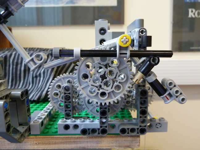 |
Now study this photo and
 movie of the escapement from the front. This time, pay attention to the single point of contact between the gravity arm and the pendulum. Notice that when the gravity arm is lifted by the escape wheel, it separates from the pendulum, with a gap of around 5mm opening up between the two. But when the gravity arm is rotating clockwise, falling under the influence of gravity, it remains in contact with the pendulum, giving the pendulum a little push. This is how energy is transferred to the pendulum, keeping it going even though there are losses due to air resistance and friction. The ultimate source of this energy is the gravitational potential energy of the falling weight (the coffee bag). At each oscillation of the pendulum, some of this energy is transferred into gravitational potential energy of the small weight at the rightmost extremity of the gravity arm, as it is lifted by the escape wheel. And then, as this small weight falls, its gravitational potential energy is used to impart a small impulse to the pendulum. movie of the escapement from the front. This time, pay attention to the single point of contact between the gravity arm and the pendulum. Notice that when the gravity arm is lifted by the escape wheel, it separates from the pendulum, with a gap of around 5mm opening up between the two. But when the gravity arm is rotating clockwise, falling under the influence of gravity, it remains in contact with the pendulum, giving the pendulum a little push. This is how energy is transferred to the pendulum, keeping it going even though there are losses due to air resistance and friction. The ultimate source of this energy is the gravitational potential energy of the falling weight (the coffee bag). At each oscillation of the pendulum, some of this energy is transferred into gravitational potential energy of the small weight at the rightmost extremity of the gravity arm, as it is lifted by the escape wheel. And then, as this small weight falls, its gravitational potential energy is used to impart a small impulse to the pendulum.
|
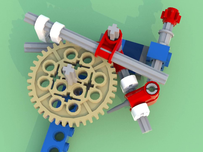 |
There are many different types of escapement mechanism. This one is an Arnfield escapement, brilliantly implemented in Lego by David Ziemkiewicz. You should check out some of David's
 other designs and also his other designs and also his  movie showing the assembly details of his Arnfield escapement. You will need to get the relative positions of the escape wheel, gravity arm and locking/release pallets exactly right. The pallets (white in David's illustration on the left) are not included in the supplied Lego kits, but are available from a demonstrator on request. You should not need the little screwdriver part featured in David's instructions, a standard pin appears to work just fine. Finally, David's design features a shock absorber, which is also not strictly necessary if you get the torques just right. movie showing the assembly details of his Arnfield escapement. You will need to get the relative positions of the escape wheel, gravity arm and locking/release pallets exactly right. The pallets (white in David's illustration on the left) are not included in the supplied Lego kits, but are available from a demonstrator on request. You should not need the little screwdriver part featured in David's instructions, a standard pin appears to work just fine. Finally, David's design features a shock absorber, which is also not strictly necessary if you get the torques just right.
|
 |
That said, getting the torques just right is a little fiddly, so here is a photo of the clock with a shock absorber in place. You could either attach it to the gravity arm mount, as in David's design, or directly to the superstructure, as in the photo on the left.
The Arnfield escapement is a type of gravity escapement, in which the impulse applied to the pendulum depends only on the fall of the gravity arm and not on the torque in the gear train. Simpler escapement designs dispense with the gravity arm, with the impulse coming directly from the escape wheel, but then accurate timekeeping requires a constant torque which is hard to achieve in practice. Over time, bearings stiffen, materials corrode and dust accumulates, all affecting the transmitted torque. Take a look at alternative escapement designs on YouTube (search
for Lego escapement). Of particular interest are
the grasshopper escapement, invented by John Harrison and used in the
clock you cannot fail to have noticed on the corner of Corpus Christi
College, the anchor escapement at the heart of the
|
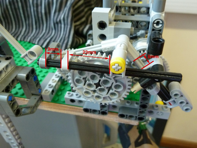 | Your Arnfield escapement will require careful fine tuning. Here are some approximate measurements to get you started. |
 |
The pendulum has a period of 1.5 seconds. According to the standard theory that
you have probably seen at school, this means it needs to be around 56cm long. But it
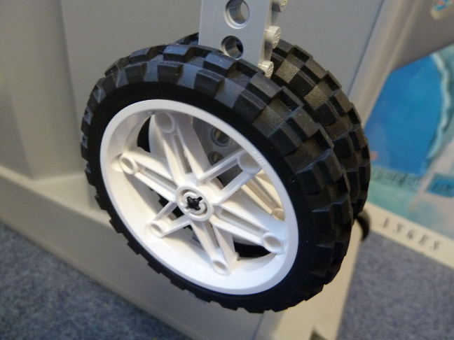
is not quite as simple as that. For starters, the standard theory assumes a point mass at the end of a "light" (i.e. zero-mass) rod. So, in practice, you will need to make the pendulum longer than 56cm, and you should also make it adjustable so that you can fine tune its period. The easiest way to do this is to build the bob (the mass at the end of the pendulum) out of a pair of tyred wheels connected through a short axle, as shown in the photo on the left. You can then regulate the clock's timekeeping by moving the bob up and down the holes in the pendulum's rod. For more on pendulums, take a look at the
 theory section of the excellent website Dr Hugh Hunt maintains about the Trinity College clock. theory section of the excellent website Dr Hugh Hunt maintains about the Trinity College clock.
|
 |
When you have built your pendulum, disconnect it from the escapement, give it a push and time how long it
takes for its amplitude to decay by 50%. This is an indirect
measure of the pendulum's quality factor,
something we are interested in for any resonant system, be it a
pendulum or an electrical tuning circuit. The longer the oscillation
takes to decay, the higher the quality. For maximum efficiency, you
want your pendulum to have as high a quality factor as possible. The way the pendulum sits on a knife-edge suspension, instead of the more obvious axle, minimises friction losses and improves the quality factor.
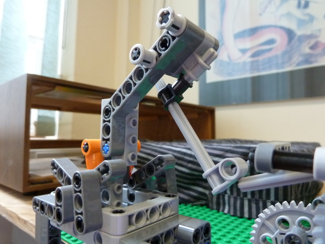
In the photo on the left, note the two sliding axle adjustments between the top of the pendulum and the point of contact with the gravity arm. You will need to replicate this sort of arrangement to get the pendulum properly aligned with the escapement. You will also need to come up with an alternative way of supporting the suspension's V-shaped beams, since the light grey rectangular pieces are not included in the supplied Lego kits. |
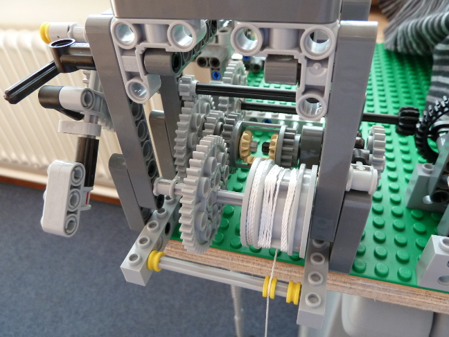 |
This photograph shows the part of the gear train that transmits torque from the falling weight to the escape wheel. The weight is attached to the end of the
string wound on the drum in the foreground. When viewed from the front (left in the photo), the drum wants to turn anticlockwise. On the same axle as the drum is a 40-tooth gear wheel which meshes with the 24-tooth wheel on the differential gear housing. The differential therefore wants to turn clockwise. On the same axle as the differential is another 40-tooth wheel, which meshes with an 8-tooth wheel, which is on the same axle as the escape wheel. The escape wheel therefore wants to turn anticlockwise. The overall gear ratio from the escape wheel to the drum is 16.67:1, so the drum will rotate once every 16.67 minutes for a 60-second escape wheel. The falling weight will therefore fall relatively slowly, but it will eventually hit the floor, at which point the clock will stop. This is why mechanical clocks need winding: we need to periodically raise the weight, thereby recharging the clock's energy reserve.
|
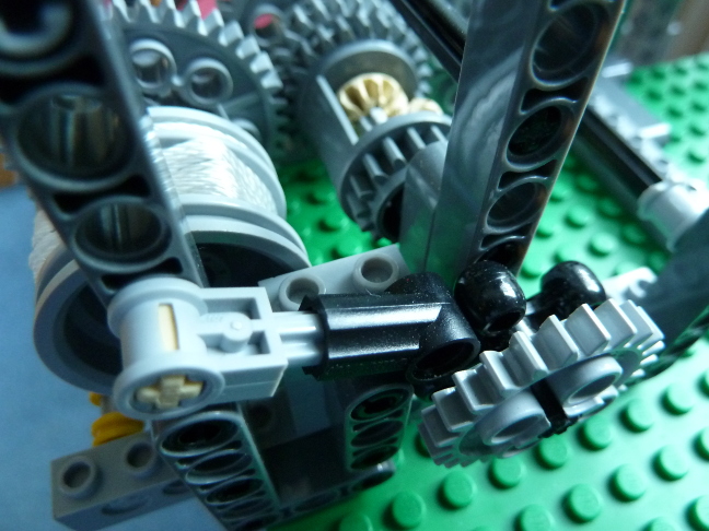 |
When we are not winding the clock, we need to make sure that the rear axle of the differential is not free to rotate. Otherwise, the weight would fall rapidly with the winding wheel spinning and no torque finding its way to the escapement. We can achieve this using the black ratchet mechanism detailed in this image. As you can see in
 this movie, the ratchet allows the axle to rotate in one direction, so that the weight can be raised. But it does not allow rotation in the other direction, so the only way the weight can fall is by driving the escapement through the gear train. The torque cannot take a short cut and spin the winding wheel. this movie, the ratchet allows the axle to rotate in one direction, so that the weight can be raised. But it does not allow rotation in the other direction, so the only way the weight can fall is by driving the escapement through the gear train. The torque cannot take a short cut and spin the winding wheel.
Regardless, to satisfy the requirements of this exercise, which stipulate that your design should incorporate at least one motor and one sensor, you will probably want to replace the manual winding mechanism with a motorized one, by attaching a motor to the rear axle of the differential. You can then dispense with the ratchet, since the motor provides the necessary resistance to the differential axle. You could either run the motor while a touch sensor is depressed, or come up with a fully automatic system for winding just before the weight hits the floor, or something in-between, depending on your coding expertise. Further details can be found in the documentation for the |
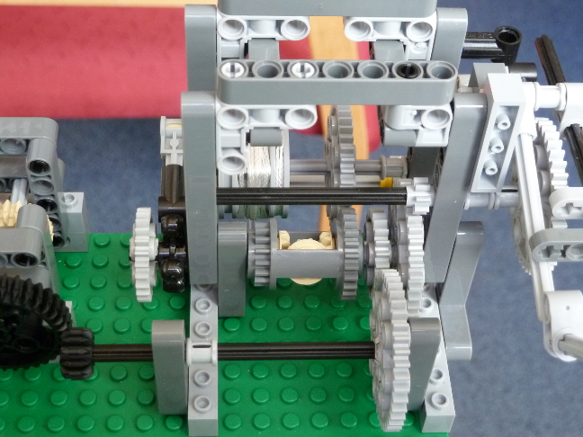 | Here is a view of the gear train from the other side. The black axle in the foreground is driven by the escape wheel via an 8:40 gear reduction (to the front differential axle) and then a 24:40 gear reduction. It therefore turns once every 8.33 minutes. At the left end of the black axle, you can see a black, 12-tooth bevel gear meshed with a black, 36-tooth bevel gear. The larger bevel gear therefore rotates once every 25 minutes. |
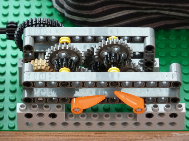 | The hands module is nothing more than a gearbox that further slows the rotation until we arrive at an axle that rotates once every 60 minutes (the minute hand, left) and an axle that rotates once every 12 hours (the hour hand, right). Starting from the black, 36-tooth bevel gear at the back left, there is a 20:24 reduction followed by a 12:24 reduction to the minute hand, which therefore rotates 2.4 times slower than the 25-minute bevel gear, as required. There is a further 1:12 reduction between the minute and hour hands. |
Here are some points to bear in mind if you decide to build your own clock.
-
For the falling weight, we suggest you use something like a pencil case. You can then add and remove pencils until you are happy with the total weight. 100g is a good starting point. Too much weight and the gravity arm will bounce (though you can tame it with a shock absorber), too little weight and the escape wheel will be unable to lift the gravity arm. Do not overload the clock, since this can cause axles to bend and gears to snap. Note, though, that with a heavier weight we could have a higher gear ratio between the weight and the escapement, and hence less frequent winding. The
 Trinity College clock has around 100kg of weights falling through several stories. It runs for 7.5 days between windings.
- Estimate the power requirement of your clock, in Watts. Where does the energy go?
- Have a go at measuring the timekeeping accuracy of your clock. If you can, vary some environmental parameters. Temperature, atmospheric pressure and air currents are all relevant. Below is a graph showing a similar Lego clock's accuracy over a four hour time period. How do you think we obtained this data? How much temperature variation would be required to explain the drift?

- Note how the torque on the gear train changes while the weight is being wound back up. What effect does this have on the timekeeping? Can you stop the gravity arm bouncing during winding, without having to add an extra load to the arm?
- Twist your pendulum through 90o so that the bob's face (as opposed to its side) has to cut through the air. What happens? Why?
- Over a period of months and years, the clock's timekeeping will be affected by parts getting worn out. Which parts do you think are the most critical in this respect?
- Feel free to add chimes and cuckoos to taste!
The prodigious pendulum clock was designed and built by Andrew Gee in November 2018, incorporating
 David Ziemkiewicz's Arnfield escapement and
  Dillon Sharlet's knife-edge pendulum suspension.
