The terrific TV camera
Is it really possible to build a TV camera using just Lego? Well, sort of. To be precise, you will need Lego and also a 99p laser pointer. And you will be building a model of a fascinating early mechanical television camera pioneered by the Scottish engineer John Logie Baird.
| Some annotated photographs | |
|---|---|
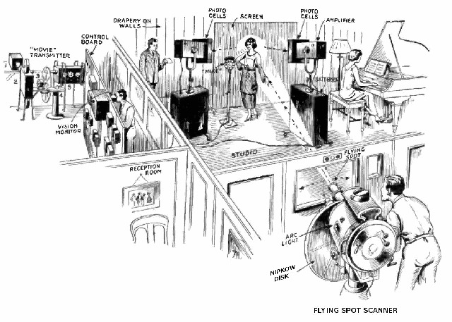 |
Early mechanical television systems operated on the flying spot camera principle. In the illustration on the left, the thing that looks like a camera in the foreground is actually a bright light fitted with a Nipkow disk. The disk has small holes cut into it, in a particular spiral pattern, with each hole allowing a narrow beam of light through into the darkened recording studio. As the disk spins, the beam of light is swept from left to right across the scene, then jumps down a little bit and scans from left to right again, and so on. Provided the disk spins fast enough, it is possible to scan, say, 120 lines at 30 frames per second. At the same time, one or more photodetectors in the studio record the light reflected off whatever is in the way of the beam. The recorded signal therefore varies with time as the beam flies across the scene. When the beam is pointing at something bright, a high voltage is recorded; when the beam is pointing at something dark, a low voltage is recorded. The signal therefore encodes the image; it can be broadcast to a remote TV receiver, and provided there is also adequate synchronisation (i.e. knowing where in the signal each frame starts, and where within each frame each line starts), it is possible to reconstruct the image and display it at the receiver. This is the essence of television. [Illustration, left, reproduced with permission from Wikimedia] |
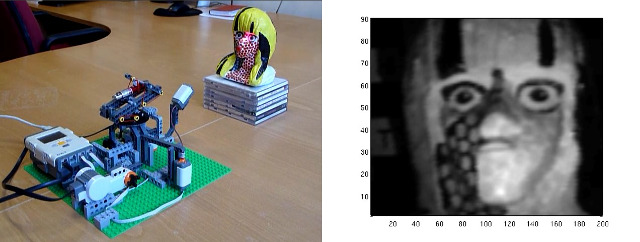 |
Here is the Lego model of a flying spot camera alongside an example of an image it captured. Instead of a bright light behind a Nipkow disk, we take the more direct route of mounting a laser pointer on a Lego turret. The turret sweeps the laser spot across the scene, while the reflected light is recorded by the Lego light sensor.  Here is a movie of the camera scanning a few lines of the image, and Here is a movie of the camera scanning a few lines of the image, and  here is another movie showing (speeded up) the acquisition of an entire frame. Although these movies were made under normal lighting conditions, you would need to put your Lego camera into a darkened environment (e.g. your team cupboard) for it to work properly. The Lego model is slow: whereas a real mechanical camera might record at 30 frames per second, the Lego model can only manage a 90-line image in around three minutes. But it does illustrate beautifully how a flying spot camera works, and the images are remarkably good for snap-fit plastic and a 99p laser pointer. here is another movie showing (speeded up) the acquisition of an entire frame. Although these movies were made under normal lighting conditions, you would need to put your Lego camera into a darkened environment (e.g. your team cupboard) for it to work properly. The Lego model is slow: whereas a real mechanical camera might record at 30 frames per second, the Lego model can only manage a 90-line image in around three minutes. But it does illustrate beautifully how a flying spot camera works, and the images are remarkably good for snap-fit plastic and a 99p laser pointer. |
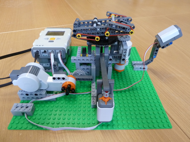 | This photograph shows the entire Lego TV camera. In the centre is the turret, at the top of the turret is a platform on which the laser is mounted, and the platform can rotate in two directions: azimuth (side to side) and elevation (up and down). The motor for the azimuth rotation is in the background, connected to the black turntable through a gear train. The motor on the left is for the elevation rotation. It is connected through a sequence of gears to a black axle that moves up and down through the centre of the turntable, attached at its top to the laser mounting platform. In the foreground is a touch sensor used for detecting when the platform is at its maximum elevation, and on the right is the light sensor used to record the light reflected off the scene, i.e. the TV signal. |
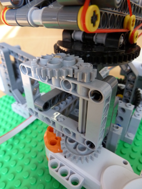 |
This photograph shows the azimuth motor and gear train. The motor (bottom) drives an 8-tooth gear which meshes with a 24-tooth gear, giving a 3:1 reduction. The 24-tooth gear drives a vertical grey axle with an 8-tooth gear at the top, which in turn is meshed with a 24-teeth gear (another 3:1 reduction). The top 24-tooth gear meshes with the 56-tooth black turntable (a further 2.33:1 reduction). The overall gear reduction from motor to turntable is therefore 21:1. You will not be able to build the gear train exactly like this, since the grey rectangular piece holding the grey vertical axle is not provided in your kit, but you should be able to build something similar with the same gear reduction. You can change the gear ratios if you have good reason to, but then you will need to change also some of the parameters in the provided  software. For example, the azimuth sweep angle is currently coded as 600 degrees of motor rotation. If, to speed up the scan, you decided to halve the gear reduction, you would also need to change the code to 300 degrees. software. For example, the azimuth sweep angle is currently coded as 600 degrees of motor rotation. If, to speed up the scan, you decided to halve the gear reduction, you would also need to change the code to 300 degrees.
|
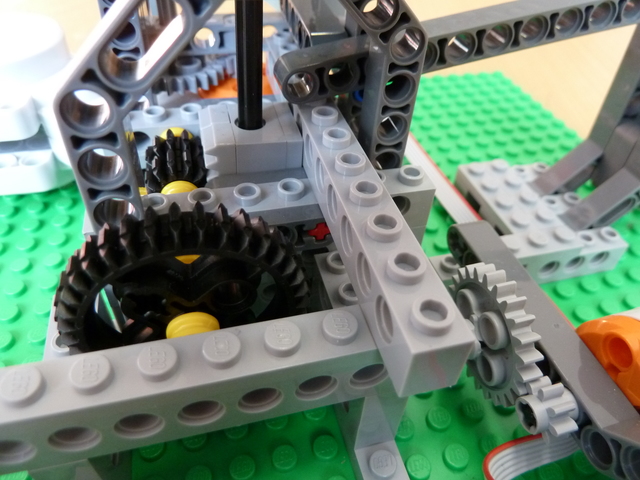 | This photograph shows the elevation motor (bottom right) and gear train. The motor is connected to an 8-tooth gear that meshes with a 24-tooth gear, giving a 3:1 reduction. |
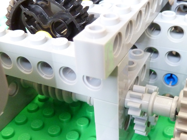 | The 24-tooth gear is on a short axle with another 8-tooth gear that meshes with a 16-tooth gear, giving a further 2:1 reduction. The 16-tooth gear is on a longer axle with a grey worm gear (bottom left) that meshes with the black 36-tooth gear, giving a further 36:1 reduction. The 36-tooth gear is on the same axle as the two black pinions that mesh with the grey rack (see previous photograph). The overall gear reduction from motor to pinions is therefore 216:1. |
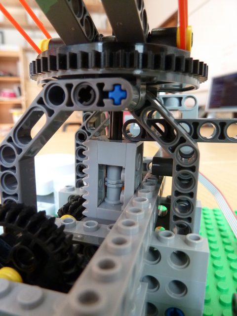 | The black pinions mesh with the grey rack which is clamped onto a black axle. Study carefully the details of this clamping mechanism. Notice how the axle is free to rotate within the clamp, but is constrained (by the friction fit of the two grey bushes) to move vertically with the rack. |
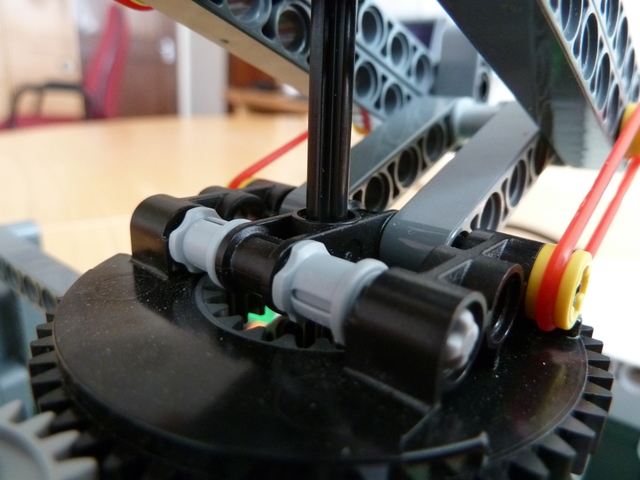 | The black axle passes through the centre of the turntable .... |
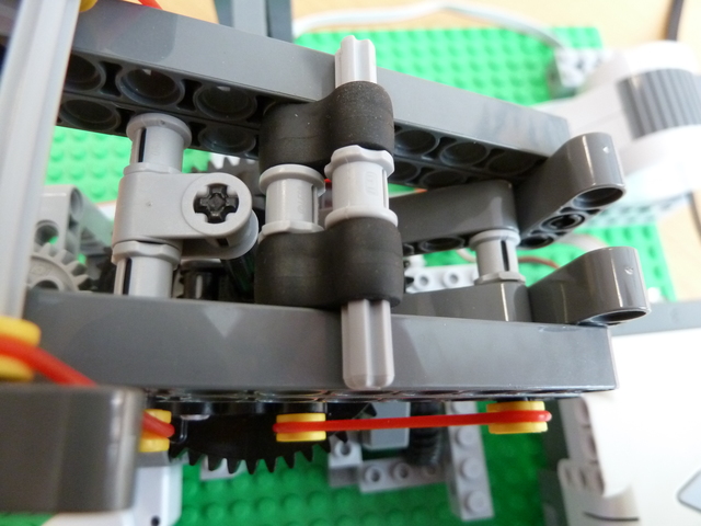 | ... and is secured at its top to the upper part of the hinged laser mounting platform. |
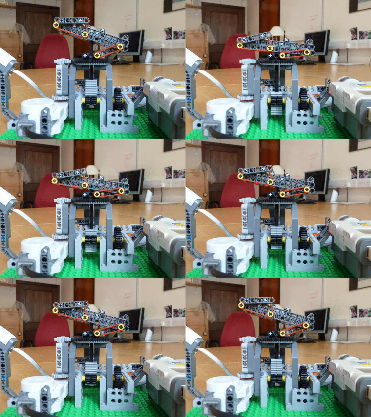 | In summary, the elevation drivetrain works like this. The important detail is that the black axle is free to rotate within the light grey clamp to which the rack is attached. The black axle needs to rotate with the azimuth motion of the platform. The clamp must be wedged between the black pinions at the front and pieces of structural Lego at the back and the sides, so the only way it can move is up and down. |
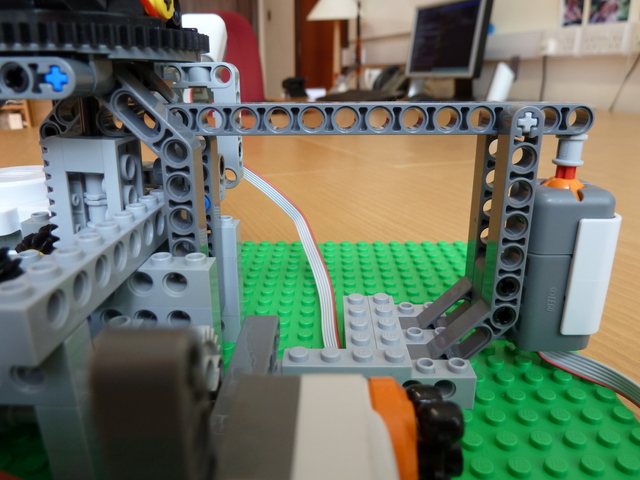 |
This is the mechanism used to detect the upper limit of the elevation motion. The left hand end of the long, dark grey beam rests on top of the light grey rack clamp. The beam is pivoted near its right hand end, where it presses down on a touch sensor. The pivot is as far to the right as possible, so a light nudge from the rack clamp is enough to activate the touch sensor. The software controlling the camera starts by raising the elevation of the laser until the touch sensor is engaged: at this point, it starts scanning the laser in a raster pattern, left to right and top to bottom. The software is provided  here. here.
|
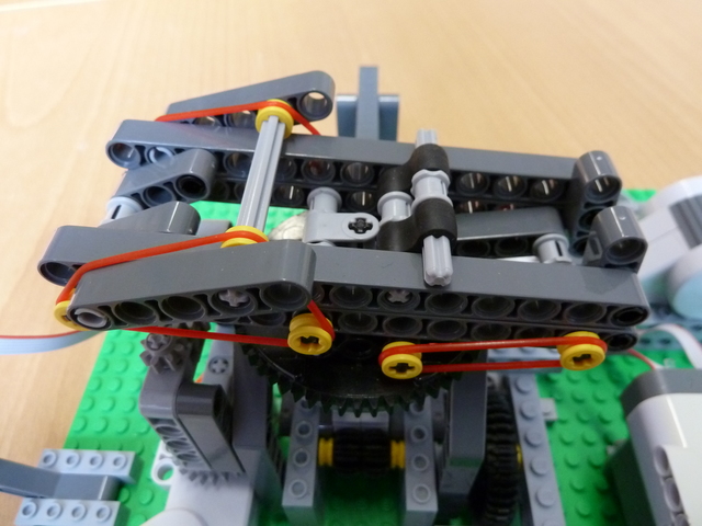 | Finally, a quick look at the top of the laser mounting platform. The laser sits securely between the various supports running down the centre of the platform. The middle support can be flicked backwards and forwards to accommodate different length lasers. The back support is redundant for the short lasers we provide, but could be useful for longer lasers. |
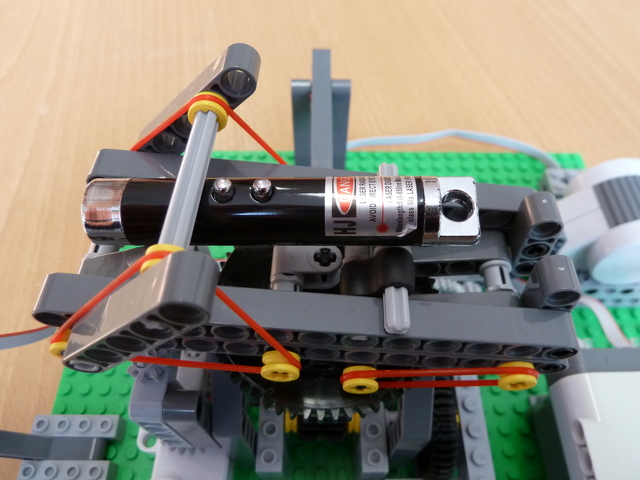 | The elasticated clamp holds the laser firmly in place. The other set of elastic bands, to the right, reduces the play in the elevation mechanism. The laser pointers we provide are low power, but the usual precautions nevertheless apply. Do not look directly into the beam. Do not scan a real face. Find something else interesting to scan! |
Here are some points to bear in mind if you decide to build your own TV camera.
- Print out
 this test card and scan it with your camera. Do the squares remain square at all positions in the image? Note the line in the
  provided software with the comment about "distortion correction". Why is this line required? Can you finesse the correction to make the squares perfect?
 - Can you speed up the camera so it acquires images faster? Is there a compromise between speed and resolution?
- Does the width of the laser beam matter?
- How is it possible that there are shadows in the images?
- What would be the advantages and disadvantages of using more than one light sensor?
| Postscript | |
|---|---|
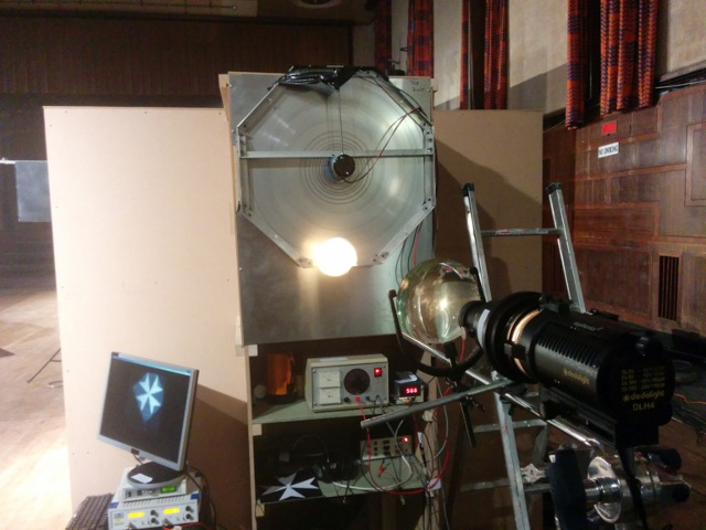 | The Lego TV camera was originally developed as part of a TV documentary about John Logie Baird and the history of television. The team, led by Dr Hugh Hunt, also built a full-size, working camera. This photograph shows the light source focused through a lens onto the rotating Nipkow disk, with the TV "studio" in the background. |
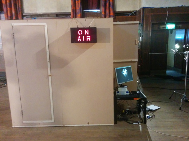 | This is a side view of the "studio", with the light source and disk on the right. The studio is little more than a windowless wooden shed, with a door to gain access. |
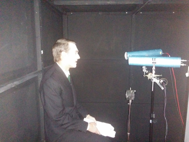 | The actor sits inside the "studio". The two blue canisters are photomultiplier tubes, very sensitive photodetectors for recording the TV signal. Note the walls painted black, to ensure that the photodetectors record just the light passing through the Nipkow disk and reflected off the actor, and not any light scattered off the walls. |
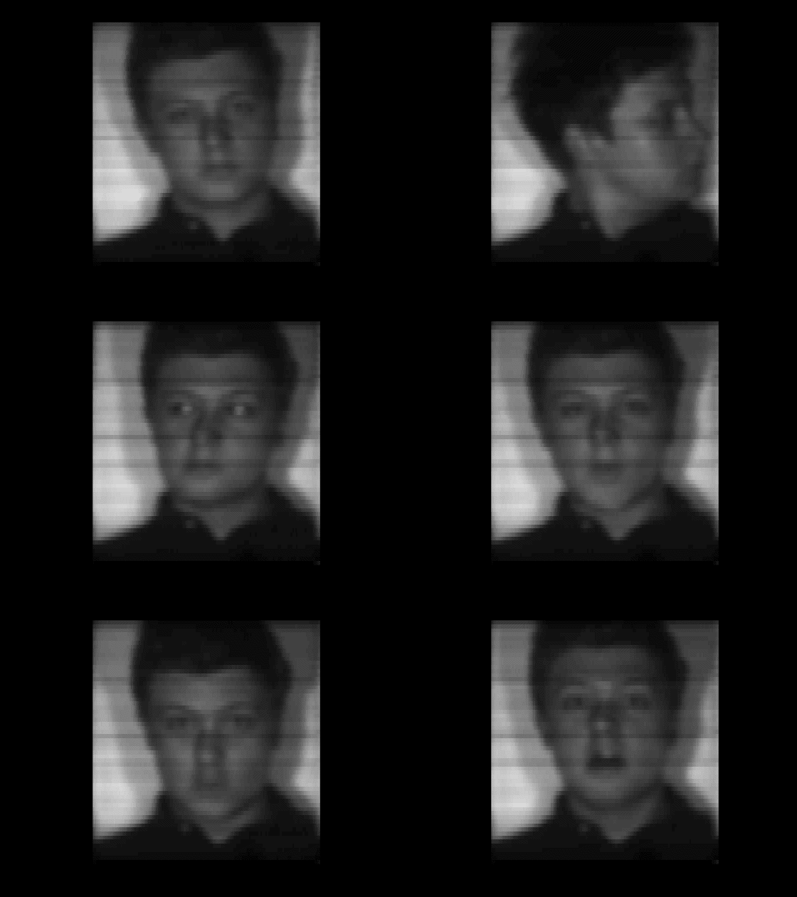 | Finally, here is a short TV clip recorded using the flying spot camera. |
The terrific TV camera was designed and built by Andrew Gee in February 2016.