The resplendent Roman balance
Despite its name, balances of this nature were in use as early as the fourth and fifth centuries B.C.E., even before Archimedes first explained the principle of the lever.
Start by having a look at the balance  in action
(mpeg movie). This is a weighing machine, capable of measuring masses
in the range 10-200g to an accuracy of around 2%. The critical phases
of operation are when the counterweight is being driven left to right
down the beam (the right to left motion is simply to return it to the
starting position). At some point during the left to right motion, the
beam passes through its balance point. This event is detected by a
light sensor near the top of the tower, pointing left. It sees a thin
Lego piece (near the top of the cradle) as it swings up in front of the
LED. The whole process is repeated three times, first with no extra
mass on the cradle, then with a known 100g calibration mass on the
cradle, and finally with the unknown mass on the cradle. Below are
graphs of the light sensor output plotted against the motor position.
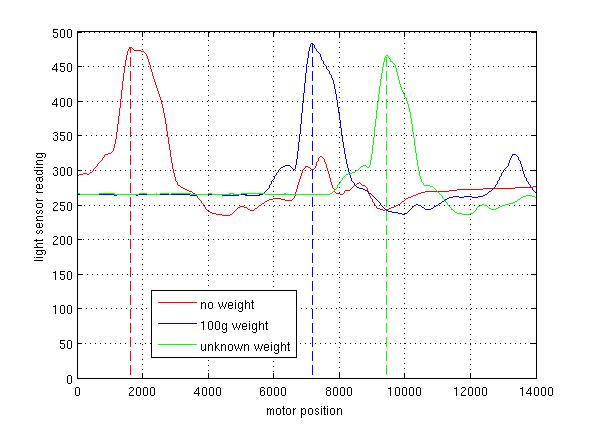
The first pass (no extra mass on the cradle) produced the red trace, with the balance point fairly close to the tower. The second pass (known calibration mass of 100g on the cradle) produced the blue trace. The final pass (unknown mass on the cradle) produced the green trace. If we assume that the balance points correspond to the peak light sensor outputs (dotted lines), then the unknown mass can be estimated using simple ratios. In this example, the reading was 141.3g. Professional postal scales put the mass at 139.3g.
Here are some points to bear in mind if you decide to build your own balance.
- The light sensor and motor position can be read using the Python code in try_light.py and try_motor.py (first session).
- The light sensor reading is typically a little noisy. The traces in the graphs above were smoothed using the same procedure used for the motor velocity in try_motor.py (first session).
- Finding the peak of a trace is covered in example_3.py (programming examples on Moodle).
- Think about the merits of the three-pass measurement protocol, including the calibration pass with a known mass. By measuring lengths and using moments, would it not be possible to use just two passes, one with no extra mass and one with the unknown mass? What would be the advantages and disadvantages of this alternative approach?
- Another way to speed up the weighing process would be to read the light sensor during the return trip too: so three balance points could be located in half the time (right to left, left to right, then right to left again). Why might it be more accurate to use the left to right sweeps only?
- How might you improve on this design to (a) measure a greater range of masses, (b) measure mass more precisely and (c) measure mass more quickly? What factors influence the beam length? What about the motor speed?
- The readings are generally more accurate when the unknown mass is less than the calibration mass. Why is this?
| Some annotated photographs | |
|---|---|
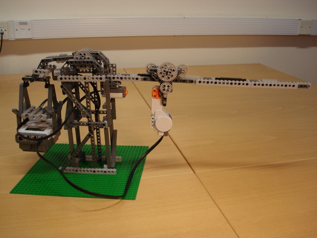 | Complete view from the front. The motor is driven right to left until it hits the touch sensor: this provides a repeatable reference point for subsequent measurements. The motor is then drive left to right, through the balance point and beyond. The balance point is detected by a thin Lego piece passing in front of the light sensor. |
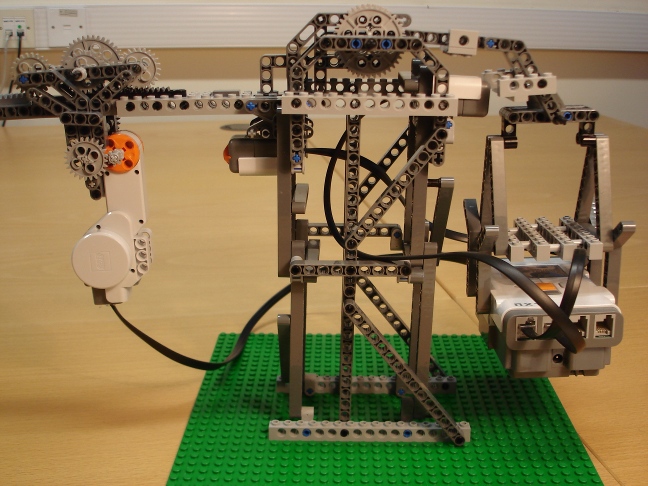 | A zoomed-in view from the back, showing all the main components (left to right): rack and pinion mechanism, touch sensor, fulcrum, light sensor and cradle. The NXT brick is a conveniently heavy mass to load the cradle. It compensates for the long beam on the other side of the fulcrum. |
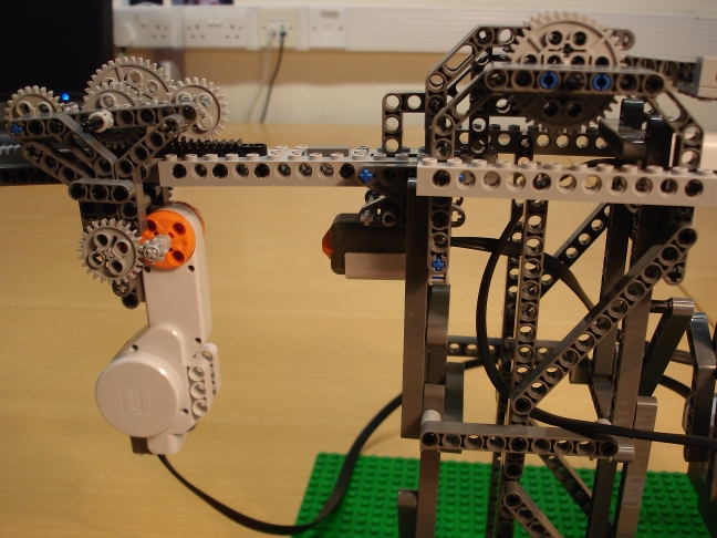 | The rack and pinion mechanism, including the gears attached to the motor drive shaft. Also in shot are the touch sensor and the fulcrum. |
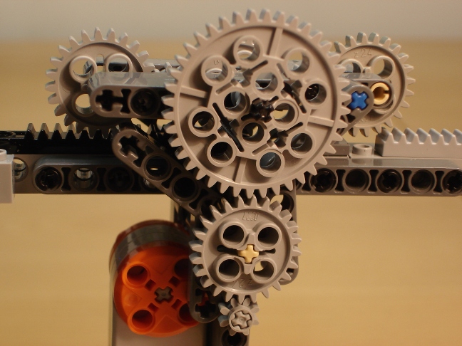 | Close-up of the rack and pinion mechanism (from the other side). There are not many rack parts in the Lego sets, but spacing them appropriately and using multiple pinions allows substantial translational motion. |
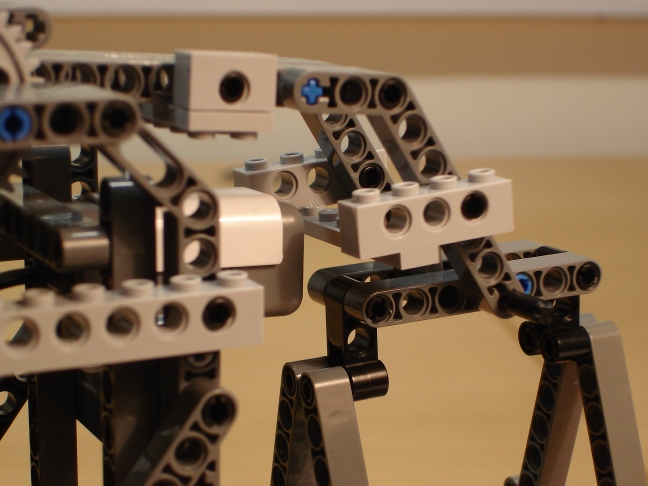 | Close-up of the light sensor (attached to the tower) and the thin Lego piece (attached to the cradle) that passes in front of it. In a one-off calibration procedure, the thin Lego piece's position is adjusted until it produces a peak light sensor response when the balance is level. |
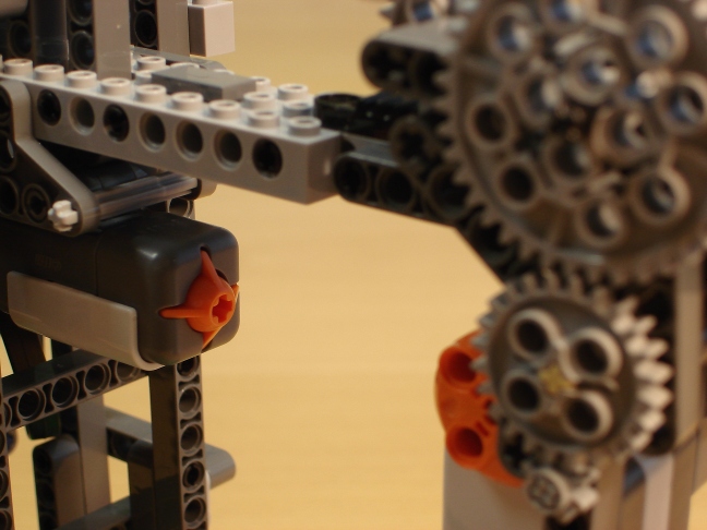 | Close-up of the touch sensor, which is used to detect when the counterweight has returned to its starting position. The software applies the brakes as soon as the touch sensor is triggered. This provides a reference starting point for the subsequent sweep when the actual measurements are made. |
The resplendent Roman balance was designed and built by Paul McMahon in January 2010.