The beguiling bender
The  three point bend test is a famous experiment in structural mechanics. You will study the
  underlying theory later this year in Part IA Paper 2 (a quick summary is provided
  here), so this is a good opportunity to get ahead by building your own bender right now. The purpose of the bend test is to estimate the
  Young's modulus of a beam. The Young's modulus is, of course, a critically important material property that is used in almost all structural design calculations.
The easiest way to understand the three point bend test is to watch this  movie of the Lego bender in action. Next, study the annotated photographs below, to better appreciate what each part of the model does. The movie and photographs provide a good starting point from which you can build your own bender, but you will need to think carefully about the fiddly details.
The Python code for the bender is given  here, almost in its entirety. However, all calibration constants have been removed, so you will need to calibrate your own model from scratch. The provided code assumes a model set up as illustrated in the movie and photographs, with two motors, a light sensor and a touch sensor. If you move away from this basic design, you will have to make corresponding changes to the Python code, though doing so may bring about some improvements.
| Some annotated photographs | |
|---|---|
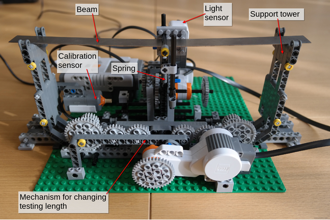 | This photograph shows the fully assembled model, which operates as follows. (1) The distance between the supports (the "testing length") is set to a predefined, initial value by the motor in the foreground of the photograph, which drives the support towers together until the touch ("calibration") sensor is triggered. (2) The second motor then extends the spring downwards via a gearbox and a chain, and the tension in this spring deflects the beam. (3) Attached to the beam is a printed barcode-style scale. This provides a way of measuring the vertical deflection of the beam using the light sensor. (4) By knowing the force (proportional to spring extension) and the deflection of the beam it is possible to calculate the Young's modulus. (5) The distance between the supports is then increased and the procedure is carried out again. Five tests are carried out: the results for each of these tests should be the same, provided the testing length is properly accounted for in the calculations. |
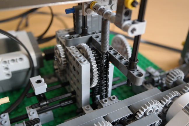 | This photograph shows the gearbox and the spring. The spring is not part of the standard Lego kit but can be provided by a demonstrator, as can the steel beam itself. The gearbox steps down the motor rotation: the gears at the output of the box rotate more slowly than at the input. You will need to account for the gear ratio in your Python code, since it relates the linear motion of the bottom of the spring to the rotation of the motor. |
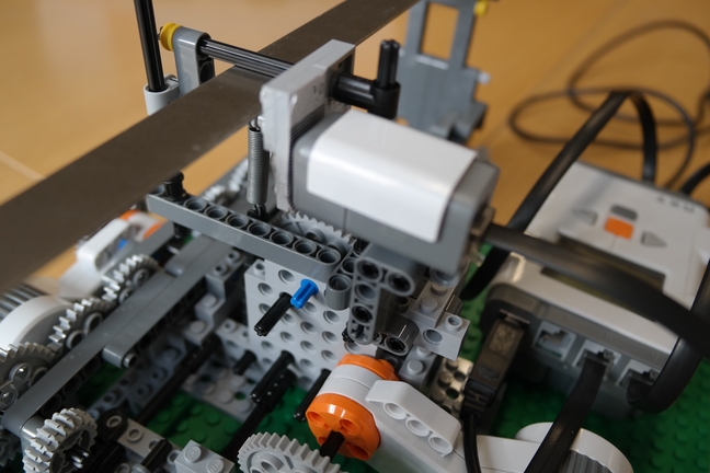 | This model does not carry out the three point test in the conventional manner. More commonly, the beam is loaded incrementally and the deflection is measured after each load increment. However, in this case the load is increased continuously and as the 'barcode' passes in front of the light sensor, the computer records the position of the bottom of the spring (and hence the applied force) as each bar goes by. Using the known distance between the bars, we can deduce the beam deflection corresponding to each force reading. Although the light sensor reading fluctuates continuously between high (bright) and low (dark), we can detect the passing of each bar by picking out the peaks and troughs in the readings. The Python code for doing this is provided: the necessary signal processing is not as straightforward as you might think, have a look at the code if you are interested. We also provide a  pdf file containing various 'barcodes'. It is up to you to choose the appropriate bar spacing and thickness from the selection on offer. There will be a trade-off between reliability and resolution of the results (i.e. the number of data points per experiment). The distance between the printed 'barcode' and the light sensor is also important and you will need to do some testing to find the best value. pdf file containing various 'barcodes'. It is up to you to choose the appropriate bar spacing and thickness from the selection on offer. There will be a trade-off between reliability and resolution of the results (i.e. the number of data points per experiment). The distance between the printed 'barcode' and the light sensor is also important and you will need to do some testing to find the best value. |
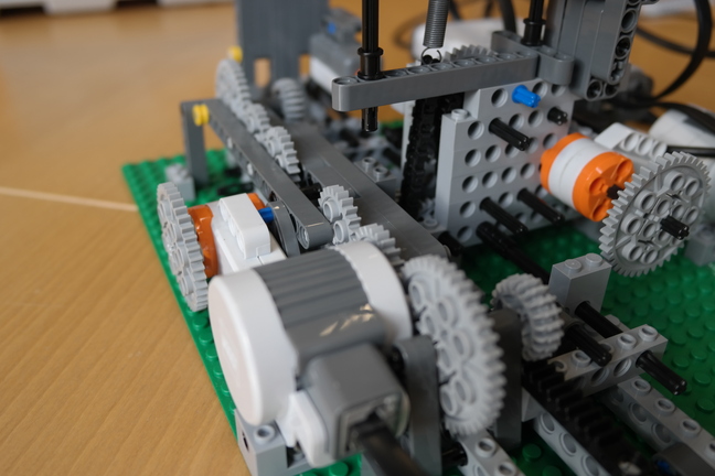 | To increase the accuracy and precision of the results, the Lego model was designed to test at a number of inter-support lengths. This is accomplished via the rack and pinion mechanism shown on the left. The mechanism is calibrated using a touch sensor, just visible in the background. This is by no means the only way to adjust and measure the testing length: there may be more efficient and accurate alternatives. |
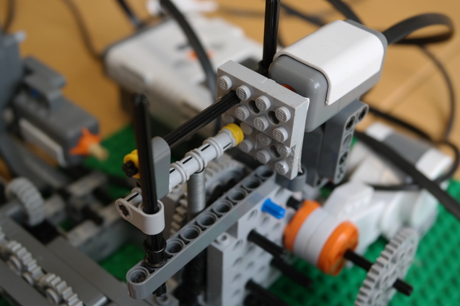 | Pictured is a close-up of the loading cage without the beam in place. The spring is attached to the bottom of the cage, with the printed 'barcode' at the back. |
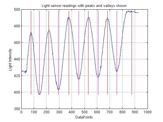 | This graph shows the raw light sensor readings with the peaks and troughs picked out by the signal processing Python code. The gradual upwards drift is because the barcode is not travelling perfectly perpendicular to the light sensor: it is important to minimze this drift. For reliable peak/trough detection, you will also need to shield the light sensor from ambient light as far as is possible, tune the prominence parameter in the  provided code, and experiment with different distances between the barcode and the light sensor. provided code, and experiment with different distances between the barcode and the light sensor. |
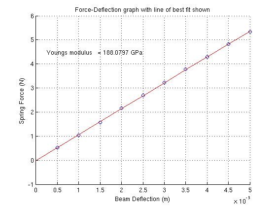 | This graph shows force plotted against deflection with the line of best fit, the result of one experiment at one testing length. It is clear that we have not gone beyond the beam's elastic limit! The Young's modulus follows from the slope of the line. See the  theory document for details of the necessary calculations. theory document for details of the necessary calculations. |
Here are some points to bear in mind if you decide to build your own bender.
- Think carefully about the structural rigidity of the supports. Any vertical deflection of these towers under load will be interpreted as a larger beam deflection. This could have a significant effect on the results, making the beam appear to be more flexible than it is.
- When we have a number of gears in series, backlash can occur. Consequently, the motor may rotate without the final gear moving. Does this matter for this model and how can any effect be minimized?
- What are appropriate gear ratios for the two drive mechanisms?
-
What is the best way to calibrate the spring? One possibility is to hang known weights from the spring and measure the corresponding displacements. Another option is to apply the theory of simple harmonic motion. The natural frequency of vibration of a mass-spring system is 1/(2*pi) * sqrt(k/m), where m is the mass attached to the spring and k is the spring constant. If you do not know where this formula comes from, click
 here for the underlying theory. For the provided springs, the frequency is rather fast so you might want to think about creative ways to measure it. For example, there are smartphone applications that estimate frequency as you tap the screen. Try searching for frequency tap in your App Store.
The beguiling bender was designed and built by Luke Redfern in November 2013.