The magnificent modular clock
Do
you know how a pendulum clock works? Do you know why mechanical clocks tick?
This is a great opportunity to learn about some remarkable machines,
with fascinating insights into mechanical engineering. Here is a  movie of the sort of clock you will build if you undertake this project. After building it, you might go on to analyse its performance in terms of timekeeping and
efficiency, and then, perhaps, improve on the design. This type of clock
is not very accurate but relatively straightforward to construct and fine tune. For
a more challenging alternative, see the
  prodigious pendulum clock.
| Some annotated photographs | |
|---|---|
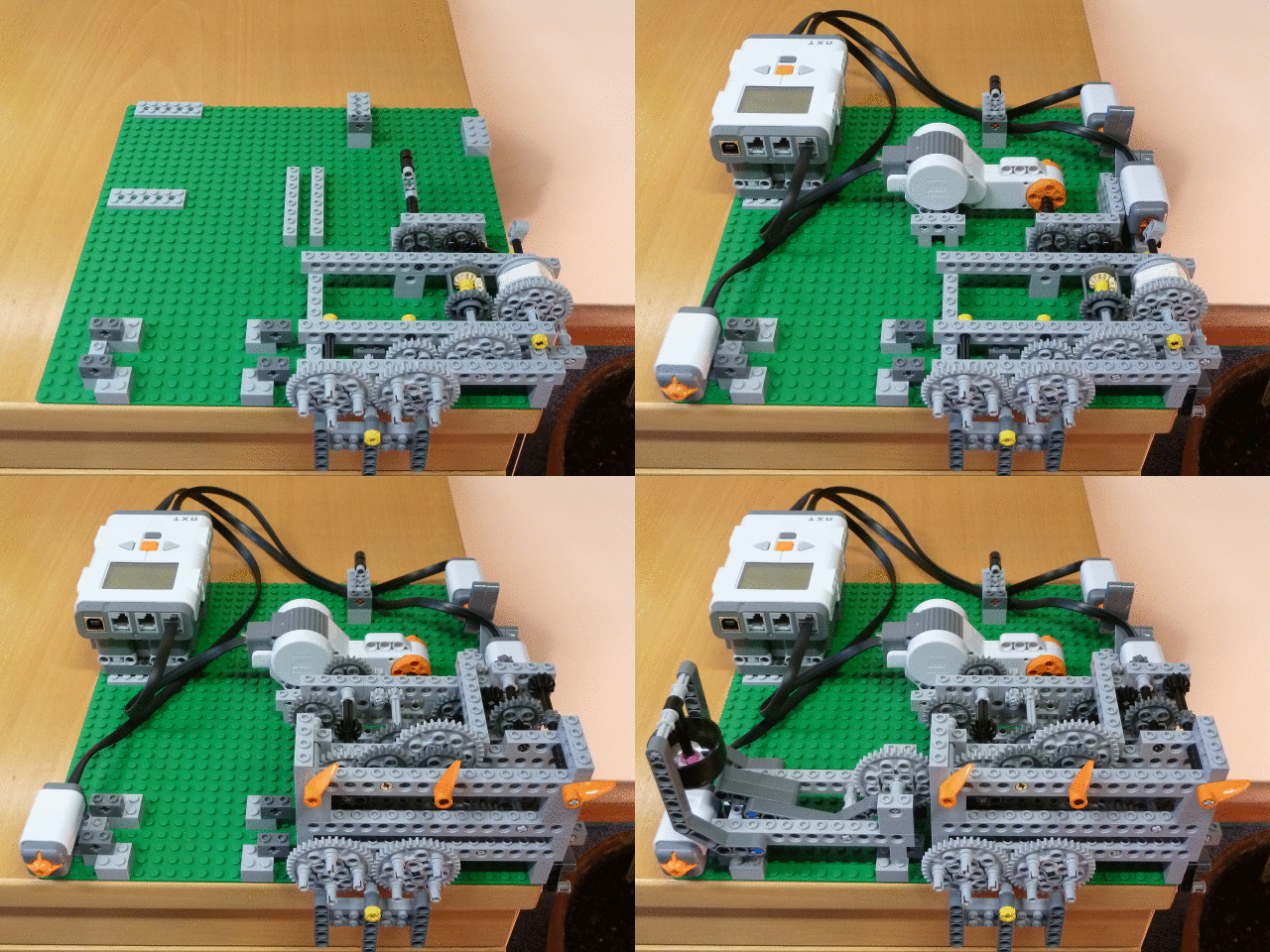 | As its name implies, this clock is modular. The animation on the left steps through its construction in four stages: (1) the base module, (2) the automatic winding apparatus, (3) the hands module and (4) the chime module. (1) The base module comprises the core components of the clock: a pendulum to regulate the timekeeping, an  escapement mechanism to convert the regular oscillations of the pendulum into regular rotation of an axle, a falling weight to drive the clock, and a mechanism to allow the weight to be wound back up, manually, without having to stop the clock. (2) The automatic winding mechanism uses the NXT motors and sensors to replace the manual wind with an automatic one. The sensors detect when the weight is about to hit the floor, and the motor then winds the weight back up, until it hits a limit switch at the top. (3) The hands module is simply a gearbox that sits on top of the base module and is driven by one of the gears in the base module. The gear ratios are calculated to arrive at axles rotating clockwise with periods of one minute, one hour and twelve hours. Orange hands are then stuck on these axles to tell the time. (4) The chime module is driven off the minute hand. Every hour, a mallet is slowly raised and then dropped as the minute hand passes sixty. The mallet hits a bicycle bell as it falls, chiming the hour. Of the four modules, you only need to build the base module and at least some of the automatic winding apparatus (to satisfy the requirements that you use at least one motor and one sensor in your design). You can then pick and choose from the other modules: you will not have enough Lego to build them all. escapement mechanism to convert the regular oscillations of the pendulum into regular rotation of an axle, a falling weight to drive the clock, and a mechanism to allow the weight to be wound back up, manually, without having to stop the clock. (2) The automatic winding mechanism uses the NXT motors and sensors to replace the manual wind with an automatic one. The sensors detect when the weight is about to hit the floor, and the motor then winds the weight back up, until it hits a limit switch at the top. (3) The hands module is simply a gearbox that sits on top of the base module and is driven by one of the gears in the base module. The gear ratios are calculated to arrive at axles rotating clockwise with periods of one minute, one hour and twelve hours. Orange hands are then stuck on these axles to tell the time. (4) The chime module is driven off the minute hand. Every hour, a mallet is slowly raised and then dropped as the minute hand passes sixty. The mallet hits a bicycle bell as it falls, chiming the hour. Of the four modules, you only need to build the base module and at least some of the automatic winding apparatus (to satisfy the requirements that you use at least one motor and one sensor in your design). You can then pick and choose from the other modules: you will not have enough Lego to build them all. |
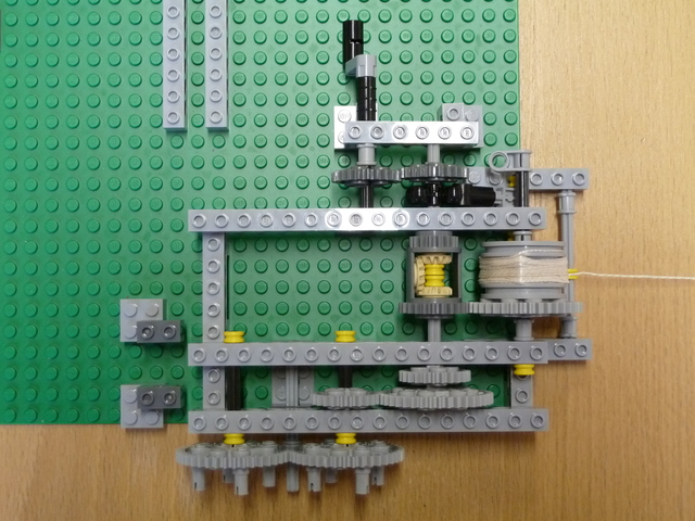 | This is an overhead view of the base module. You should be able to build it, and have a ticking clock, in an hour or two. To understand how it works, start with the string on the right. The falling weight is attached to the end of this string. The string is wrapped around a light grey drum. Pulling on the string causes the drum to rotate, and also the light grey 40-tooth gear on the same axle as the drum. This in turn causes the dark grey differential gear to rotate (more about this later). On the same axle as the differential, but nearer the front of the clock, are two light grey gears. The smaller of these plays no part in the operation of the base module, its purpose is to mesh with the hands module when the latter is mounted above the base module. The larger, 40-tooth gear is meshed with the 24-tooth gear to its left, which is mounted on the same axle as the rightmost of the two 40-tooth escapement wheels at the front. Essentially, torque is transmitted from the drum through the gear train to the two escapement wheels at the front. As shown in this image, without the pendulum in place, pulling on the string would cause the escapement wheels to rotate freely. |
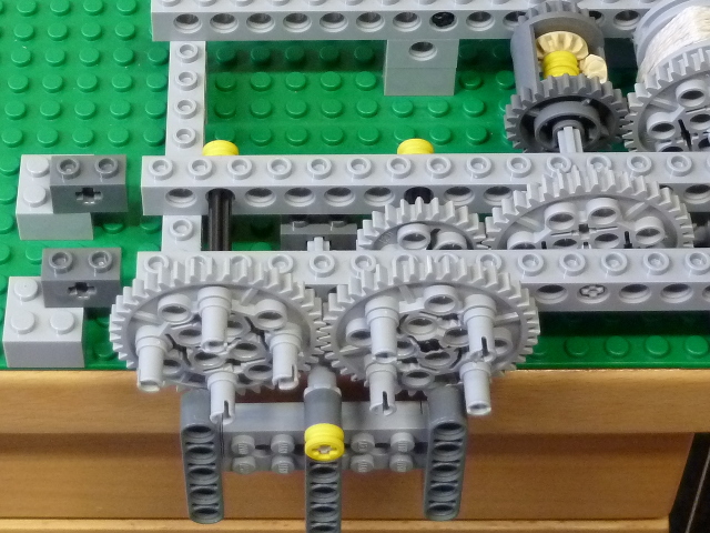 | Now
it is time to understand how the escapement mechanism works. Look carefully at this image, which shows the pendulum attached to the axle mounted centrally below the escapement wheels. Without the pendulum attached, the escapement wheels can rotate freely. But the pendulum interferes with the wheels' rotation. Specifically, there are two short arms at the top of the pendulum which collide with the light grey pins protruding from the front of the escapement wheels, preventing them from rotating apart from when the pendulum has swung to one extreme of its motion. At this point, a pin can slip past the pendulum and the wheels can rotate a little, until they are locked once more by one of the pins on the other escapement wheel. This is best appreciated by studying the middle section of  this movie. Note how the oscillations of the pendulum regulate the rotation of the escapement wheels, and hence the rotation of all the axles in the clock. This is the essence of how a clock keeps time: the pendulum oscillates at a steady rate, and hence the axles rotate at steady rates. We just need to add appropriate gears until we arrive at an axle rotating once per minute, stick some sort of pointer on this axle, and we have a second hand. Further gears and axles will then get us to hour and minute hands. Returning to the escapement, note how the light grey pins give a little impulse to the pendulum as they push past: this is what keeps the pendulum going, a transfer of energy from the gear train to the pendulum. Without this, friction and air resistance would cause the pendulum's oscillations to decay and eventually stop. this movie. Note how the oscillations of the pendulum regulate the rotation of the escapement wheels, and hence the rotation of all the axles in the clock. This is the essence of how a clock keeps time: the pendulum oscillates at a steady rate, and hence the axles rotate at steady rates. We just need to add appropriate gears until we arrive at an axle rotating once per minute, stick some sort of pointer on this axle, and we have a second hand. Further gears and axles will then get us to hour and minute hands. Returning to the escapement, note how the light grey pins give a little impulse to the pendulum as they push past: this is what keeps the pendulum going, a transfer of energy from the gear train to the pendulum. Without this, friction and air resistance would cause the pendulum's oscillations to decay and eventually stop. |
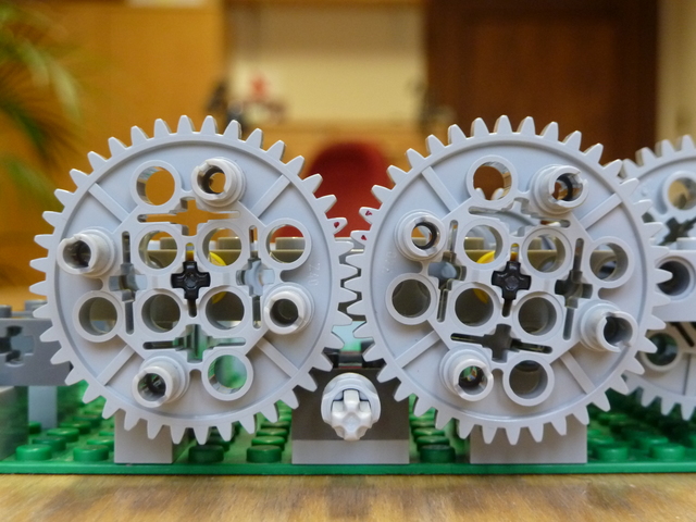 | Here is a close-up view of the escapement with the pendulum removed. This escapement design is by Ben Van de Waal: click
 here to see more of Ben's beautiful Lego escapements. This one is essentially an here to see more of Ben's beautiful Lego escapements. This one is essentially an
 anchor escapement. While straightforward to build, an anchor escapement is not as good as the anchor escapement. While straightforward to build, an anchor escapement is not as good as the
 gravity escapement used in the gravity escapement used in the  prodigious pendulum clock, since the impulse imparted to the pendulum depends on the torque in the gear train. Any progressive change in this torque (wear, lubrication, humidity) and the timekeeping of the clock will be affected. Before moving on to study the rest of the base unit, note some details of the escapement design. The dark grey brick through which the pendulum axle passes is raised off the baseplate by a thin grey plate: this is essential for proper alignment of the pendulum with the escapement pins. Also, the point at which the two wheels mesh does matter: get this wrong, and the clock's tick will be uneven at best. You can find the correct mesh point by trial and error. prodigious pendulum clock, since the impulse imparted to the pendulum depends on the torque in the gear train. Any progressive change in this torque (wear, lubrication, humidity) and the timekeeping of the clock will be affected. Before moving on to study the rest of the base unit, note some details of the escapement design. The dark grey brick through which the pendulum axle passes is raised off the baseplate by a thin grey plate: this is essential for proper alignment of the pendulum with the escapement pins. Also, the point at which the two wheels mesh does matter: get this wrong, and the clock's tick will be uneven at best. You can find the correct mesh point by trial and error. |
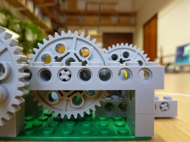 | One final detail. In order to get the pendulum to sit centrally between the two escapement wheels, you will need to offset the base module's frame laterally by half a hole. See the mounting detail at the right of this image, noting how the long, light grey studded brick (through which the various axles pass) overhangs the edge of the baseplate by half a hole. |
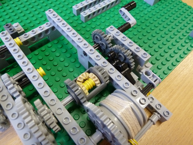 |
Now let's look at the mechanism to manually wind the weight onto the drum. This needs to be done periodically, before the weight hits the floor, otherwise the clock will stop. The crank handle at the top of the image is where you wind from: see
 this movie of the base module being wound manually. The crank turns the two dark grey 24-tooth gears (they might be light grey in your sets). The second of these 24-tooth gears powers the rear input of the differential. this movie of the base module being wound manually. The crank turns the two dark grey 24-tooth gears (they might be light grey in your sets). The second of these 24-tooth gears powers the rear input of the differential.  Differentials are wonderful bits of mechanical engineering. They are mostly used to allow the inner and outer wheels of a car to Differentials are wonderful bits of mechanical engineering. They are mostly used to allow the inner and outer wheels of a car to  turn at different speeds when the car is cornering. The best way to understand how a differential works is to build one out of Lego and play with it. Briefly, however, torque always follows the path of least resistance through a differential. So if we power the rear input, and the front input is not free to rotate (since the pendulum locks the escapement most of the time), the torque will instead cause the dark grey differential housing to rotate, which will wind the drum and raise the weight. All this while maintaining the torque on the escapement wheels, so the clock keeps ticking happily away. One little detail: the two dark grey 24-tooth gears are not strictly necessary, you could instead connect the crank directly to the differential input, but this might make things a little cramped when you come to add the automatic winding apparatus. Moving the crank away from the winding drum makes space for any sensors you might introduce to monitor the rotation of the drum. Also, the little bevel gears inside the differential may be light grey in your sets, not beige. turn at different speeds when the car is cornering. The best way to understand how a differential works is to build one out of Lego and play with it. Briefly, however, torque always follows the path of least resistance through a differential. So if we power the rear input, and the front input is not free to rotate (since the pendulum locks the escapement most of the time), the torque will instead cause the dark grey differential housing to rotate, which will wind the drum and raise the weight. All this while maintaining the torque on the escapement wheels, so the clock keeps ticking happily away. One little detail: the two dark grey 24-tooth gears are not strictly necessary, you could instead connect the crank directly to the differential input, but this might make things a little cramped when you come to add the automatic winding apparatus. Moving the crank away from the winding drum makes space for any sensors you might introduce to monitor the rotation of the drum. Also, the little bevel gears inside the differential may be light grey in your sets, not beige. |
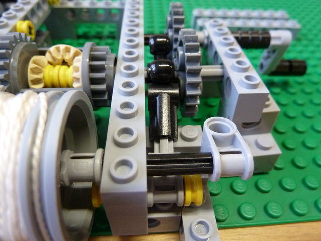 | When we are not winding the clock, we need to make sure that the rear input of the differential is not free to rotate. Otherwise, the weight would fall rapidly with the crank spinning and no torque finding its way to the escapement. We can achieve this using the black ratchet mechanism detailed in this image. As you can see in
 this movie, the ratchet allows the axle to rotate in one direction, so that the weight can be raised. But it does not allow rotation in the other direction, so the only way the weight can fall is by driving the escapement through the gear train. The torque cannot take a short cut and spin the winding crank. this movie, the ratchet allows the axle to rotate in one direction, so that the weight can be raised. But it does not allow rotation in the other direction, so the only way the weight can fall is by driving the escapement through the gear train. The torque cannot take a short cut and spin the winding crank. |
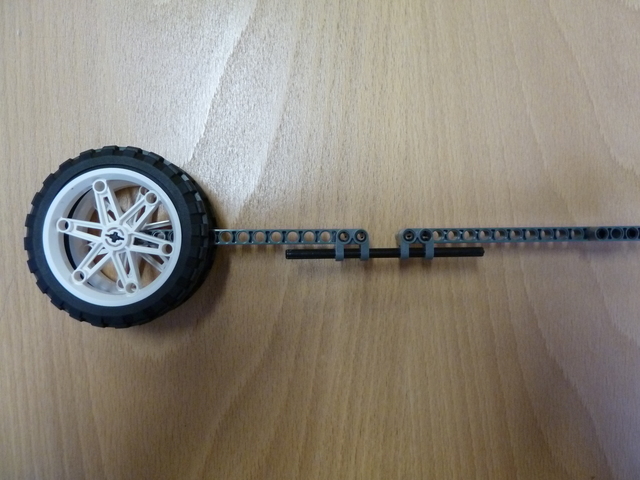 | The top end of the pendulum requires two side arms to collide with the escapement pins: see the middle section of  this movie for details. At the bottom, you should place some sort of heavy bob made out of wheels and tires, and near this some sort of friction-fit adjustment mechanism. This allows you to fine tune the length of the pendulum, and hence the period of its oscillation. this movie for details. At the bottom, you should place some sort of heavy bob made out of wheels and tires, and near this some sort of friction-fit adjustment mechanism. This allows you to fine tune the length of the pendulum, and hence the period of its oscillation. |
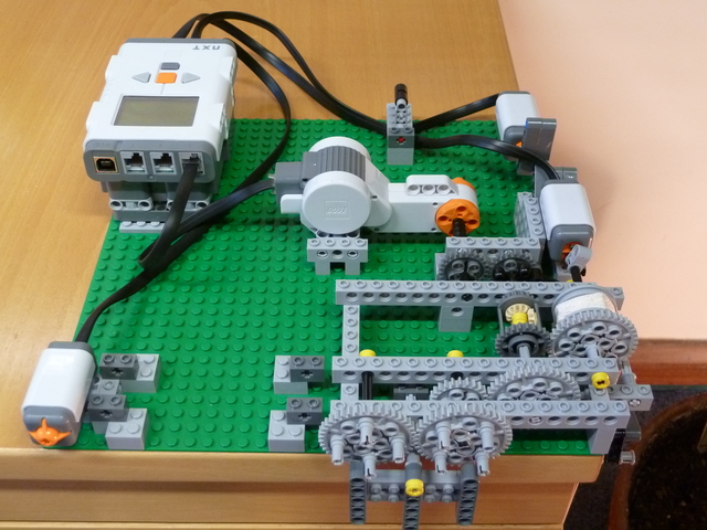 | This image shows the base module with the addition of the automatic winding apparatus. Shown here, and also at the start of  this movie, is the "top of the range" solution, requiring significant coding expertise to make work robustly. The winding crank has been replaced with a motor. There is also a light sensor counting rotations of the small, light grey piece at the end of the drum axle. When a certain number of rotations has been counted (this number depending on the height of the table), the motor is started and the weight is wound up, until it collides with a limit switch, at which point the motor is shut off. To be more precise, the weight collides with a lever which presses the touch sensor at the back right of the baseplate. There is a second touch sensor at the front left, which can be used to stop the automatic winding program and/or manually wind the clock. Processing the signal from the light sensor, to count revolutions of the drum axle, is not trivial. If you do not have sufficient coding expertise, a simpler approach is to dispense with the light sensor, with winding initiated by pressing the front-left touch sensor and terminated by the limit switch. An even easier option is to dispense also with the limit switch: simply press the touch sensor to wind the clock, and release it to stop winding. this movie, is the "top of the range" solution, requiring significant coding expertise to make work robustly. The winding crank has been replaced with a motor. There is also a light sensor counting rotations of the small, light grey piece at the end of the drum axle. When a certain number of rotations has been counted (this number depending on the height of the table), the motor is started and the weight is wound up, until it collides with a limit switch, at which point the motor is shut off. To be more precise, the weight collides with a lever which presses the touch sensor at the back right of the baseplate. There is a second touch sensor at the front left, which can be used to stop the automatic winding program and/or manually wind the clock. Processing the signal from the light sensor, to count revolutions of the drum axle, is not trivial. If you do not have sufficient coding expertise, a simpler approach is to dispense with the light sensor, with winding initiated by pressing the front-left touch sensor and terminated by the limit switch. An even easier option is to dispense also with the limit switch: simply press the touch sensor to wind the clock, and release it to stop winding. |
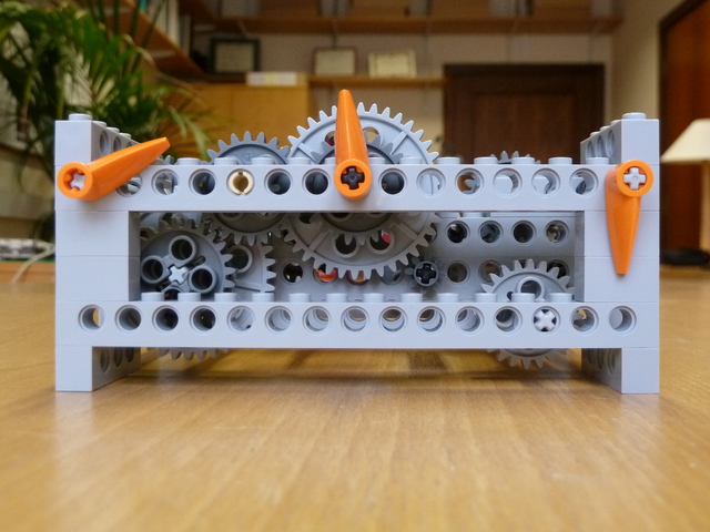 | Here is the hands module. It is simply a gearbox that meshes with one of the axles in the base module. The pendulum length is adjusted until this axle rotates with a convenient period: i.e. a plausible factor of sixty seconds, so that a functioning second hand can be realised with the available Lego gears. Further gear reductions are used to drive the minute and hour hands off the second hand. You may not have sufficient Lego to implement all three hands, in which case one or two hands would be fine. |
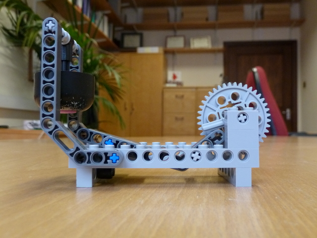 | And here is the chime module. The 40-tooth gear meshes with the hands module and rotates anticlockwise with a period of one hour. On the same axle as the gear wheel is a short, light grey arm. In the image, it is just about to start pressing down on the right part of the dark grey mallet, thereby lifting up the left part. After a while, the light grey arm will slip past the rightmost edge of the mallet which will then fall, striking the bell on the way down. You can see this happening at the end of  this movie. If you build a chime module, you will need to scavenge for something that rings. In this example, it is the outer shell of a cheap bicycle bell. this movie. If you build a chime module, you will need to scavenge for something that rings. In this example, it is the outer shell of a cheap bicycle bell. |
Here are some points to bear in mind if you decide to build your own modular clock.
-
For the falling weight, we suggest you use something like a pencil case. You can then add and remove pencils until you are happy with the total weight. 100-150g is a good starting point. Do not overload the clock, since this can cause the gears to snap. Note, though, that with a heavier weight we could have a higher gear ratio between the weight and the escapement, and hence less frequent winding.
 Trinity College's pendulum clock has around 100kg of weights falling through several stories. It runs for 7.5 days between windings.
- Estimate the power requirement of your clock, in Watts. Where does the energy go?
- Does the torque on the gear train change while the weight is being wound back up? If so, what effect does this have on the timekeeping?
-
For a challenging extension exercise, you might consider replacing the escapement with another one of
 Ben Van de Waal's designs.
- Have a go at measuring the clock's accuracy over an extended period of time.
- Twist your pendulum through 90o so that the bob's face (as opposed to its side) has to cut through the air. What happens? Why?
The magnificent modular clock was designed and built by Andrew Gee in October 2015.