The dexterous domino layer
This exercise works at several different levels. Superficially, you get to build a mobile robot that drives around while depositing dominoes at regular intervals. You can then have fun toppling them once the robot has done its work. At another level, you gain experience designing and building some interesting mechanisms, not least the mechanism to push the dominoes out onto the table as the robot travels along. Finally, the exercise provides a nice introduction to the mechanical engineering topics of  forward and
  inverse kinematics. In the context of the domino layer, forward kinematics is all about predicting the pattern of dominoes given the way we drive the vehicle's wheels. In contrast, the harder problem of inverse kinematics is about calculating the necessary wheel speeds to arrive at a desired domino layout. We provide here sufficient
  theory and
  Python code to design a robot that can lay dominoes in a circle of specified radius: see this
  movie of the domino layer in action. You might then wish to go further and try other domino patterns.
| Some annotated photographs | |
|---|---|
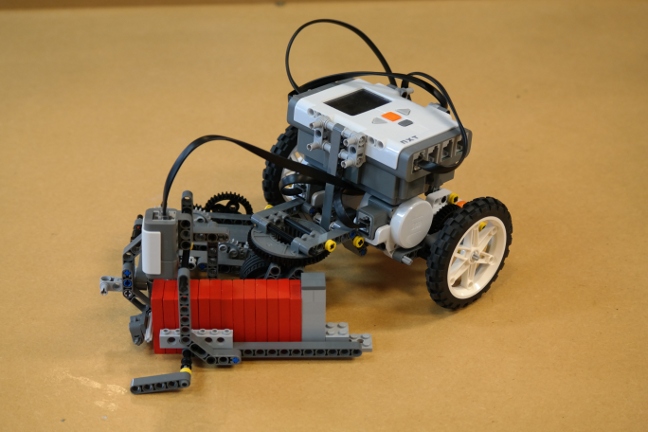 | This photograph shows the fully assembled domino layer. The vehicle is articulated, meaning it has pivoting sections. The front section holds the NXT brick and two motors that power the front wheels independently. The motors can be driven at different speeds to induce a turning effect or at the same speed to travel in a straight line. The rear section is a little more complex. Below the pivot is a trolley wheel which rotates as the vehicle turns (think of a supermarket trolley). Attached to the trolley wheel is the domino laying mechanism. The dominoes are stacked in a hopper and are always in contact with the table. They are pushed out by a piston rod. The gearing on the far side of the photograph ensures that the dominoes are spaced at suitable intervals. All of the power for the rear half of the model comes from the trolley wheel being driven by the tabletop. |
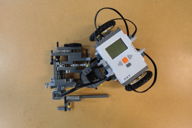 | This is a view from above the vehicle, where it is easier to see that the two sections are independent. The light sensor, above the domino guide rails, is used to stop the robot when the dominoes have run out. In the previous photograph, you can see a book-end style piece that is used to keep the dominoes upright and as a marker for the light sensor. |
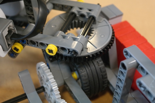 | This photograph shows a close-up view of the pivot, which is built using the Lego turntable part. You are free to redesign this as you see fit, but some sort of pivot is essential to keep the focus of the exercise on forward and inverse kinematics. |
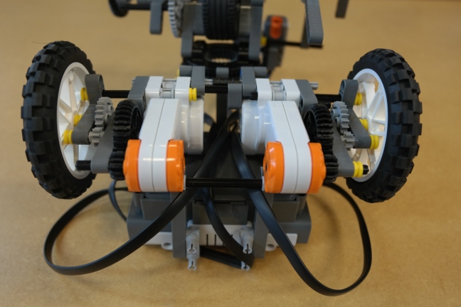 | Here we see the underside of the front part of the vehicle. The gearing steps down the rotation of the motors to increase torque and precision at the wheels. The gear ratios could be stepped down even further to provide greater control. |
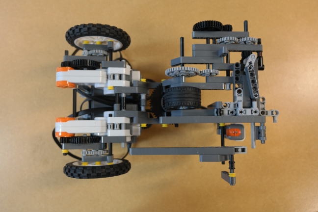 | Pictured here is the underside of the entire vehicle, showing clearly how power is transferred from the trolley wheel to the piston. The rotation is stepped up twice to achieve an appropriate spacing between dominoes. The gear ratios need to be carefully thought through: if stepped up too much then the trolley wheel could slip as the resistive torque is too high; not enough and the dominoes will be too far apart for toppling. At the far right of the photograph is the piston mechanism. As the light grey Lego piece rotates, the connecting rod (dark grey) oscillates the axle (light grey) back and forth, pushing the dominoes out at regular intervals. Note that the domino spacing will be different when the vehicle is turning to when it is driving in a straight line. |
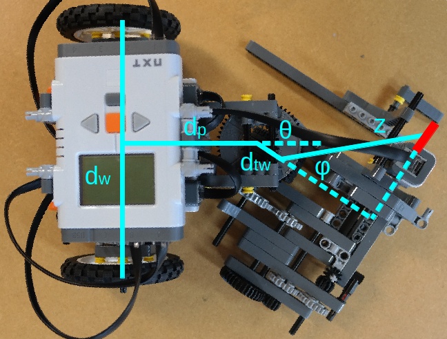 | Here we see the critical kinematic lengths and angles superimposed on a photograph of the robot. You will need to measure the lengths on your finished robot before applying the  theory to work out the motor speeds for a circular domino layout. We provide theory to work out the motor speeds for a circular domino layout. We provide  Python code for the inverse kinematics calculations, though you will need to write your own code to actually drive the robot once you have worked out the motor speeds. Python code for the inverse kinematics calculations, though you will need to write your own code to actually drive the robot once you have worked out the motor speeds. |
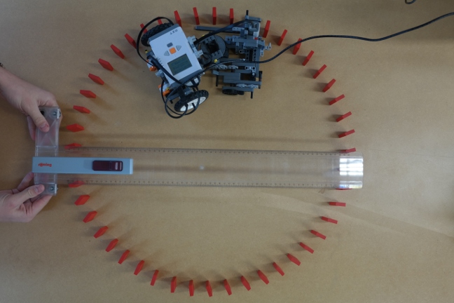 | At the end of this exercise, you should be able to plot a domino circle of a specified radius and then topple it. The example on the left shows an experiment where we aimed for a 60cm radius and verified the outcome with a ruler. |
Here are some points to bear in mind if you decide to build your own domino layer.
- Our prototype robot needs to be reloaded every twelve or so dominoes. Could a larger, automatic hopper be incorporated into your design?
- In this design, the dominoes are always in contact with the table. When the hopper is full, the first domino experiences a lot of friction and the piston has to apply a large force to eject it. Consequently, the domino is fired out with some vigour. When there are fewer dominoes in the hopper, they slide out more easily. This leads to irregularities in the domino chain, visible in the plan view of the circle above. Can you think of a way to mitigate these problems?
- There is still an unused motor in the kit. Could this be put to use, perhaps as part of a larger hopper or a different laying mechanism?
- Can any get your robot to lay dominoes in other shapes?
The dexterous domino layer was designed and built by Luke Redfern in January 2014.