The greatest gearbox
It is fairly rare for a motor to be directly coupled to whatever it is driving: instead, drive is normally transmitted through a  gearbox. Some examples of fixed gearboxes are those found in wind turbines, pumps or even the Lego NXT motors you will be using (these have a
  48:1 gear reduction). Fixed gearboxes might be used to set the correct operating point, allowing power to be transferred with maximum efficiency. Sometimes we need variable gearboxes, which allow different gears to be selected depending on the current drive requirements. For example, bicycle gears enable the cyclist to ride at their preferred cadence independent of the current road speed.
This model Lego transmission system is similar to that found in a car: it has five forward gears, a reverse gear and a manual clutch. There are several areas in which the basic design can undoubtedly be improved: some suggestions can be found at the bottom of this page. You should consider any changes you want to make before getting too far into the build, as careful planning will save you time.
Below is a series of photographs showing the different parts of the model and explaining what they do. There is also a  movie showing the gearbox in action. The Python code for the model is given
  here, almost in its entirety: you will just need to tune some constants in the code to match the physical characteristics of your model. However, if you improve the basic model, for instance by automating the clutch, you will need to make the necessary changes to the software yourselves.
| Some annotated photographs | |
|---|---|
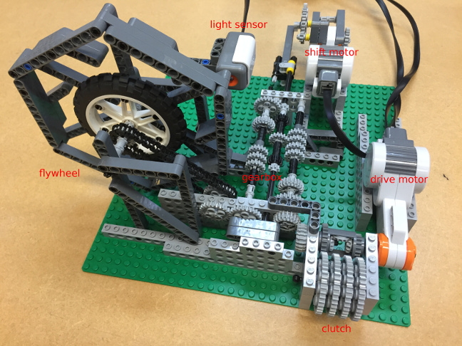 | This photograph shows the fully assembled model. When you run the supplied code, the drive motor turns but no power is transferred to the gearbox until you engage the clutch, by arresting the rotation of the four large grey gear wheels. When engaged, the clutch sends power through the gearbox to the flywheel. The two touch sensors (not shown in this photograph, but see the  movie) are used to shift up and down. Pressing the two touch sensors simultaneously stops the drive motor. The light sensor records the rotation of the flywheel. movie) are used to shift up and down. Pressing the two touch sensors simultaneously stops the drive motor. The light sensor records the rotation of the flywheel. |
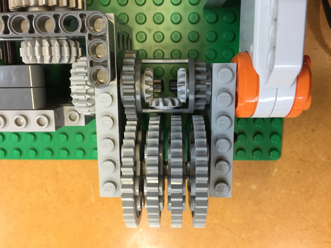 | This photograph shows the clutch, which makes use of the dark grey differential gear housing.  Differentials are normally used to allow a car's outer drive wheel to rotate faster than the inner wheel during a turn. Here, we re-purpose the mechanism to create a clutch. When the four large grey gears are unrestrained, the drive motor just causes the outer housing of the dark grey differential (and hence the large grey gears) to spin, since this is much less effort than driving the gearbox and the flywheel: the torque follows the path of least resistance. This can be seen in the first six seconds of the Differentials are normally used to allow a car's outer drive wheel to rotate faster than the inner wheel during a turn. Here, we re-purpose the mechanism to create a clutch. When the four large grey gears are unrestrained, the drive motor just causes the outer housing of the dark grey differential (and hence the large grey gears) to spin, since this is much less effort than driving the gearbox and the flywheel: the torque follows the path of least resistance. This can be seen in the first six seconds of the  movie. Arresting this spin, by manually restraining the large grey gears (at the six second mark in the movie. Arresting this spin, by manually restraining the large grey gears (at the six second mark in the  movie), causes power to be transferred through the three small gears inside the differential, and on to the gearbox itself. You will notice that, in the lower gears, very little clutch control is necessary to start or change gear. However, if you attempt to abruptly start in the higher gears, the bricks may pull off the base, analogous to "stalling" a car. Similarly, when changing gear, the gears may crunch. To stop the model from stalling and crunching, you will need to gradually engage the clutch by slowly increasing the torque on the large grey gears. This is analogous to the clutch control required to drive a car with a manual transmission. movie), causes power to be transferred through the three small gears inside the differential, and on to the gearbox itself. You will notice that, in the lower gears, very little clutch control is necessary to start or change gear. However, if you attempt to abruptly start in the higher gears, the bricks may pull off the base, analogous to "stalling" a car. Similarly, when changing gear, the gears may crunch. To stop the model from stalling and crunching, you will need to gradually engage the clutch by slowly increasing the torque on the large grey gears. This is analogous to the clutch control required to drive a car with a manual transmission. |
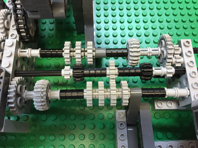 | The gearbox itself has five forward speeds and one reverse. This photograph shows the gearbox engaged in first gear. Torque is transferred from the input axle (bottom), through the central axle and on to the output axle (top). At any one time, only one pair of gear wheels is meshed between the input and central axle (in this photograph, the two identically sized light grey gears just right of centre), and one pair between the central and output axle (the small light grey gear and the larger light grey gear, further to the right). |
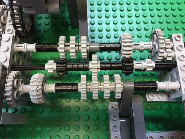 | To change gear, the central axle shifts left (changing up) or right (changing down), causing two different pairs of gear wheels to mesh, with different numbers of teeth and therefore different speed ratios. This photograph shows the gearbox in second gear, with the torque transmitted from the input axle to the central axle through the two identically sized light grey gears in the middle, and from the central axle to the output axle through the black and grey bevel gears a little to the right. When the gears are stationary, the central axle does not slide very freely. This is largely due to the mechanical properties of the straight Lego gears that dominate the inventory. While the bevelled gears mesh fairly easily, the straight gears are prone to jamming since they are not in the right orientation to slide past each other. The situation is improved if the gears are spinning when you change gear. Reverse gear (top-right as pictured) is particularly problematic: this is partly due to the straight gears, but is exacerbated by the gears attempting to mesh while rotating in opposite directions. The supplied software ignores the reverse gear, but you can try it by hand if you like. |
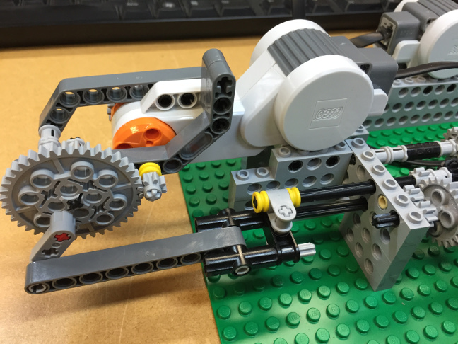 | This photograph shows the mechanism used to slide the central axle left and right. There is a kinematic mechanism to translate the large grey wheel's rotational motion into a linear motion, via a  crank and a crank and a  connecting rod. connecting rod. |
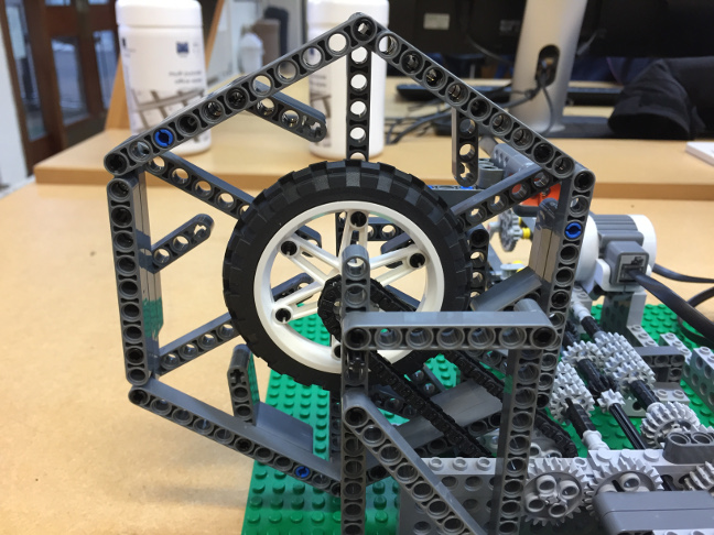 | This photograph shows the flywheel attached to the gearbox's output. It represents the inertia of the car or whatever it is the gearbox is driving. As the flywheel rotates, the light sensor picks up the spokes as they pass by, producing a signal that can be processed to measure the output speed. |
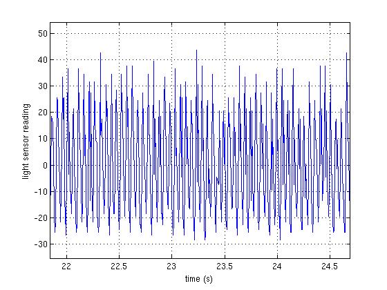 | This figure shows some of the output from the light sensor. As the wheel spins, the passing spokes reflect the light emitted by the sensor's LED, giving peaks in the readings. Suppose we wish to use these readings to measure the gearbox's output speed. It is possible to count the number of peaks per unit time and convert this to a rotational speed. However, algorithms for automatic peak detection are not trivial in the presence of varying ambient lighting conditions and noise. A more elegant solution is to investigate the frequency content of the signal using Fourier analysis. |
 | You have probably come across Fourier analysis before, without realising it. On the left is a typical example of a music visualization which you might have seen on your music player or mobile phone. It shows, in real time, the frequency content of the music, with the bass (low frequencies) to the left and the treble (high frequencies) to the right. To produce this visualization, your music player is calculating the spectrum (i.e. frequency content) of the music signal using a  Fast Fourier Transform (FFT). You will study the relevant mathematics in the first and second years of the engineering course, but this does not stop you using an FFT right now! Fast Fourier Transform (FFT). You will study the relevant mathematics in the first and second years of the engineering course, but this does not stop you using an FFT right now! |
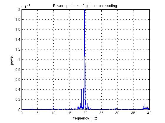 | This figure shows the spectrum of the light sensor readings. The result of an FFT is a set of complex numbers, representing the amplitudes and phases of the various frequency components. The supplied Python code plots the squared magnitudes of these complex numbers, which we loosely term the "power spectrum". We can use the FFT to calculate the gear ratio without having to count the teeth on all the meshed gear wheels. The dominant peak is at approximately 19.5Hz. Since there are six spokes on the flywheel, this corresponds to a flywheel rotation of 19.5*60/6 = 195rpm. The drive motor was running at 130rpm (the supplied Python code displays the drive motor speed continuously), giving a gear ratio of 195:130 or 1.5:1. |
Here are some points to bear in mind if you decide to build your own gearbox.
- Can you improve the reverse gear and engage it automatically?
- Can you build a mechanism to automate the clutch?
- Can you adapt the model to enable higher torque transfer without the gears skipping?
- The model accounts for
 backlash when changing gear by specifying an additional rotation in the program. So, when the direction of the shift motor changes, it first rotates a little to account for the backlash, then the necessary amount to shift gear. Can you think of an alternative, mechanical method to eliminate the backlash?
 - Modify the code to continuously display the current gear ratio.
- Modern car gearboxes have only two axles with pairs of gears that do not slide. Instead, the gears sit on the axles and are permanently meshed. Not all the gears are clamped to the axle,
 some of them can rotate freely: only when they are locked on, using a
  dog clutch, do they transmit drive. This solves the problem of meshing, giving smoother gear shifts and longer lasting gears. You can do this in Lego too, but the necessary parts are not in the provided kits. We do have a small number of them available, so ask a demonstrator if you would like to experiment. The parts will be issued on a first-come first-served basis.
The greatest gearbox was designed and built by Matt Parker in February 2015.