The twitchy trailer
This exercise is about mechanical engineering and control. Specifically, you get to build a vehicle with power transferred to the rear drive wheels through a  differential. The front wheels are steered by a realistic steering mechanism. The vehicle tows a trailer through a pivot, so what we have is a scaled down model of an articulated lorry. You can have fun driving your vehicle around, but where it really gets interesting is when you try to drive in reverse. If you have ever tried this for real, you will know how difficult it is. An articulated trailer, moving in reverse, is inherently unstable. It is a bit like trying to balance a broom vertically on your hand. Engineers call this sort of set-up an
  inverted pendulum, and it has become a classic test case for evaluating automatic control strategies.
Have a look at this  movie, which shows various attempts to control the reversing vehicle. What may not be obvious from the movie, but is central to understanding how the system works, is that the pivot angle of the trailer is being measured continuously, in real time. The control algorithm then adjusts the steering in response to changes in this angle, using an approach known as
  PID control. In a PID algorithm, there are three constants which need tuning: the proportional, integral and differential gains. It is up to you to find the best gains for different reversing scenarios. While you will need to build your own vehicle, we do provide all the necessary Python code.
The software comes in two files.  run_trailer.py is the top-level file which you will need to edit (to set the controller gains and other parameters) and run. There are three modes of operation. In drive mode, you start the trailer moving forward (up arrow) or reverse (down arrow), then steer it manually using the left and right arrows, and then finally hit the space bar to stop. In reverse mode, the control algorithm takes over and attempts to drive the vehicle in reverse while holding the trailer's pivot angle constant. In drive_then_reverse mode, you drive the vehicle forward while recording the pivot angle as a function of time: when you stop, the reversing controller takes over and attempts to retrace the vehicle's steps using the recorded pivot angles. run_trailer.py calls methods in
  trailer.py. While there is no need to edit this file or even understand what it does, it must remain in the same folder as run_trailer.py. If you do decide to explore trailer.py, perhaps for an extension exercise, start with the _reverse() method which contains the PID control code.
| Some annotated photographs | |
|---|---|
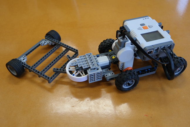 | Pictured is the complete vehicle and trailer model. The trailer is free to rotate about an axis at the rear of the vehicle. The pivot angle is measured in real time using a cunning Lego orientation sensor, discussed in more detail later. Two motors are used to power the car: one to steer and one to drive. Feel free to change the design as you see fit, as long as the essential components (drive, steering, pivot, orientation sensor) are all there. |
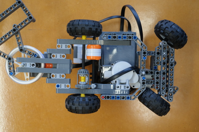 | Here is a photograph of the underside of the vehicle. The design is relatively simple and adaptable. In general terms, the front half of the vehicle is dedicated to steering while the rear half is about drive and angle sensing. |
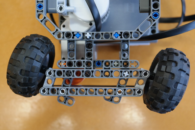 | This is a close-up view of the steering mechanism. Here are some  instructions for building a similar mechanism (courtesy of instructions for building a similar mechanism (courtesy of  http://nxtprograms.com/NXT2/race_car/). You may modify this design as you see fit, but bear in mind the need for the steering to be fast and precise. http://nxtprograms.com/NXT2/race_car/). You may modify this design as you see fit, but bear in mind the need for the steering to be fast and precise. |
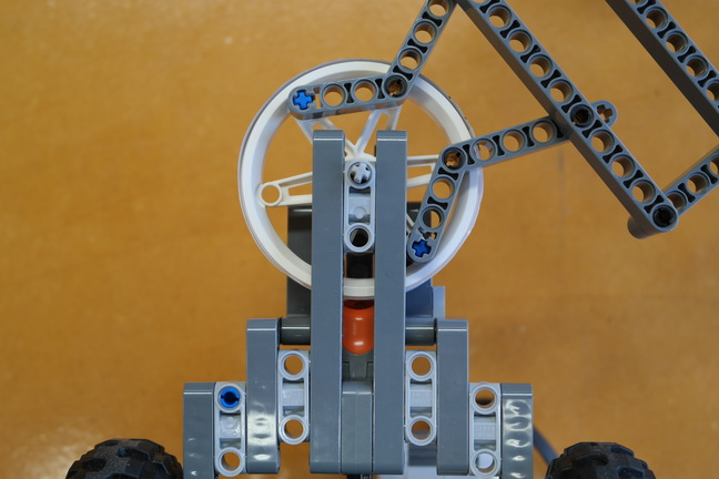 | This is a bottom view of the orientation sensor used to measure the pivot angle. This measurement is required by the automatic control algorithm, since the goal is to hold the angle constant (reverse mode) or have it follow a predetermined sequence (drive_then_reverse mode). The orientation sensor uses a Lego light sensor, which is protected from ambient light variations by some shrouding (see the top photograph). However, in this photograph the shrouding has been removed for clarity. |
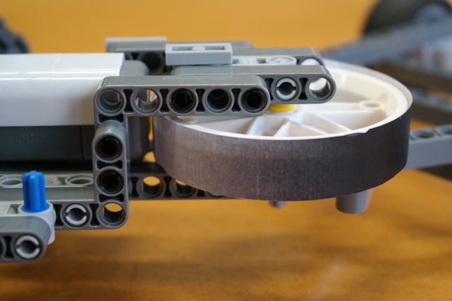 | The light sensor is pointing at the rim of a Lego wheel onto which we have taped some paper printed with a black-grey-white scale. As the trailer pivots, the light sensor finds itself pointing at a different intensity of grey and its reading changes. This is how we build a cunning orientation sensor out of Lego.  Here are some different scales for you to experiment with. They all wrap around the wheel and you can tape the ends together for a friction fit. The scales have different gradients and some will be better suited to particular scenarios than others, depending on the required trade-off between sensitivity and range. You must ensure that the neutral configuration (with the trailer in line with the car) produces a light sensor reading roughly in the middle of its range. To do this, run the try_light.m program (provided in the first timetabled Lego session) while manually swinging the trailer from neutral, to far left and then to far right. If the neutral reading is not near the centre of the range, slide the paper scale around the wheel as necessary and try again. Here are some different scales for you to experiment with. They all wrap around the wheel and you can tape the ends together for a friction fit. The scales have different gradients and some will be better suited to particular scenarios than others, depending on the required trade-off between sensitivity and range. You must ensure that the neutral configuration (with the trailer in line with the car) produces a light sensor reading roughly in the middle of its range. To do this, run the try_light.m program (provided in the first timetabled Lego session) while manually swinging the trailer from neutral, to far left and then to far right. If the neutral reading is not near the centre of the range, slide the paper scale around the wheel as necessary and try again. |
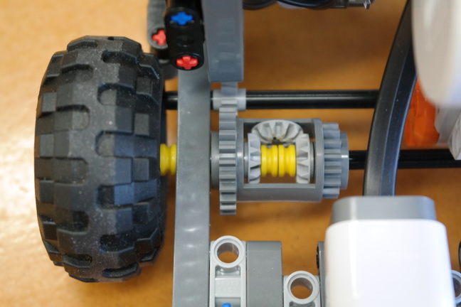 | Power is transferred from the motor to the rear wheels through a  differential. Differential gearing allows the drive wheels to turn at different speeds, which is highly desirable when cornering. The workings of a differential are explained in this wonderful differential. Differential gearing allows the drive wheels to turn at different speeds, which is highly desirable when cornering. The workings of a differential are explained in this wonderful  tutorial from the 1930s. The differential casing (dark grey) is powered by the small gear (light grey) on the upper axle. This small gear can be slid across to disengage the power, just like a neutral gear on a car's gearbox. tutorial from the 1930s. The differential casing (dark grey) is powered by the small gear (light grey) on the upper axle. This small gear can be slid across to disengage the power, just like a neutral gear on a car's gearbox. |
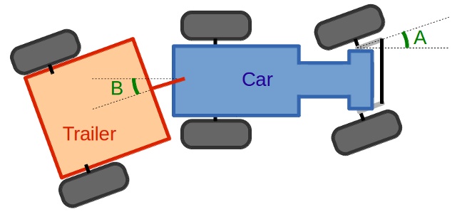 | This diagram shows the geometry of the vehicle. A is the steering angle and B is the pivot (articulation) angle. Ideally, we would calibrate the mapping between pivot angle, in degrees, and the light sensor reading, but it is more straightforward to use the light sensor reading directly as a surrogate measure of the pivot angle. The controller error is therefore given by Error = Current Light Reading - Target Light Value, and we can estimate its derivative and integral in real time (take a look at the code in reverse.m). These values are then used to determine the required steering angle as follows: Steering Angle = Error * Proportional Gain + Rate of Change of Error * Derivative Gain + Integral of Error * Integral Gain. You can tune the controller by tweaking the values of the three gains in the file trailer.m. This sort of  PID control is similar to that used in the sizzling steam engine and millions of other real-world engineering systems! PID control is similar to that used in the sizzling steam engine and millions of other real-world engineering systems! |
Here are some points to bear in mind if you decide to build your own reversing trailer.
- At present, the software assumes that the initial steering angle is zero, and you need to manually zero the steering before running the program. Can you modify the software and hardware to have the steering zero automatically?
- How does changing the trailer's length affect reversing stability? You might consider having the trailer lengthen automatically, under software control. That way, you could design and run a series of experiments to investigate the impact of trailer length.
- Instead of retracing its steps, you might program the vehicle to perform a pre-recorded parallel parking routine. You could then, perhaps, use the ultrasonic sensor to identify parking spaces as the vehicle drives along. The vehicle could then reverse into the first parking space it finds.
- What are the consequences of using the light sensor reading as a surrogate for the pivot angle? Try to calibrate the relationship between angle and sensor reading, then use the angle in the PID controller. Also experiment with different length black-grey-white scales on the orientation sensor.
The twitchy trailer was designed and built by Luke Redfern in March 2014.