In order to acquire RF data using Stradwin, two things are necessary:
See the documentation which comes with the Gage CompuScope [5] card for information on installing the card and libraries. Stradwin has been tested against the Gage CompuScope 14100 and 14200 cards, but should work with other (similar) variants of this card, so long as they have similar functionality, are supported by the Gage libraries, and have sufficient on-board memory to store one entire frame of RF data.

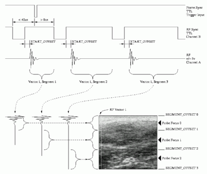
The diagram above shows which signals are required from the ultrasound machine, how they should be connected, and how they are used to construct the B-scan. Three signals are required: a once-per-frame sync (connected to the external trigger of the CompuScope), a signal which is high when the RF data is valid (connected to Channel B of the CompuScope) and the (focused, i.e. after summation) received RF signal (connected to Channel A of the CompuScope). Note that Stradwin assumes that each RF vector, or column of the B-scan, is acquired in monotonic spatial sequence, and that multiple transmit foci result in multiple RF signals, in increasing order of focal depth. A given ultrasound machine may or may not conform to this specification - please contact us [3] if you wish to use Stradwin to acquire RF data, but your ultrasound machine differs slightly from these assumptions.
The number of acquired RF signals, and which parts of these signals are used to create a B-scan, are all determined by the probe configuration file (see below) and the settings of the image source configuration dialog. In particular, the START_OFFSET, SEGMENT_OFFSETS and number of RF vectors are all defined in the probe configuration file, whereas the number of foci are defined in the image source configuration dialog. An example is shown above for the first vector of a B-scan acquired using three transmit foci.
It is also possible to sample the RF signal using an external clock, if one is available. An appropriate clock signal (see the documentation which comes with the Gage CompuScope [5] card) must be connected to the 'external clock' input, and the approximate frequency of this clock specified in the probe configuration file. The frequency must be in the allowable range for single channel acquisition.
The probe configuration files are ASCII files with names 'probe*.cfg', where * can be anything, containing the required information on each probe in use. Each line of the file contains either a comment (preceded by a '#' symbol), white space, or a property label followed by its value. The file contains general probe configuration information (which must come first) followed by configuration for 50MHz, 100MHz and external sampling rates (which can come in any order after the general configuration). Each of the sampling rate sections can be omitted if not required.
If the data was stored in IQ format, then no filter coefficients should be supplied, and the baseband frequency can be specified using PROBE_BASEBAND_FREQ.
A sample probe configuration file, complete with comments, is given below:
######################################################################
# General probe configuration
######################################################################
# The name of the probe for display in the Advanced RF Controls window
PROBE_NAME Diasus 10-22MHz

# The radius to the top of each RF vector, in cm, if using a convex probe
# If the probe is not convex, do not include this line.
# The start angle (for IVUS probes) controls the angle at which the first
# vector is plotted to construct the image.
PROBE_RADIUS       6.0
PROBE_START_ANGLE  0.0

# The radius to the probe face for mechanical 3D probes, in cm, the total
# number of probe steps, and the corresponding full scale angle,
# in degrees
PROBE_MOTOR_RADIUS 1.5
PROBE_MOTOR_STEPS  432
PROBE_MOTOR_FOV    79.043

# The number of vectors (columns), possible focal zones, and the space
# between each vector in cm.
PROBE_VECTORS      127
PROBE_SEGMENTS     14
PROBE_VECTOR_SCALE 0.0205

# The pulse shape (values in MHz). These values are only used for strain
# imaging.
PROBE_CENTRE_FREQ   16.5
PROBE_BASEBAND_FREQ 20.0
PROBE_BANDWIDTH     3.7

# The number, then corresponding labels for each of the matched filter pairs
# These should end with a set which can be used for frequency compounding
# in this case starting with the 10-13MHz filter
PROBE_FILTERS 6 broadband 10-22MHz 10-13MHz 13-16MHz 16-19MHz 19-22MHz
PROBE_COMPOUNDING_FILTER  2

######################################################################
# Configuration for 50MHz sampling rate
######################################################################
# The start of the RF vector relative to the Channel B RF Sync, in 50MHz samples
PROBE_50M_START_OFFSET    28

# The focal zone boundaries, starting at zero, and ending beyond the max probe depth, in 50MHz samples
PROBE_50M_SEGMENT_OFFSETS 0 234 338 442 545 649 753 857 961 1123 1351 1675 2227 3364 5000

# The filter length and delay
PROBE_50M_FILTER_LENGTH   21
PROBE_50M_FILTER_HALF     10

# Sets of matched real and imaginary (hilbert) filters, appropriate for 50MHz
# The first number is the filter number, the remainder are the coefficients
PROBE_50M_REAL_FILTER 0 -4110 0 -5135 0 -6018 0 -6699 0 -7128 -0 58262 -0 -7128 0 -6699 0 -6018 0 -5135 0 -4110
PROBE_50M_IMAG_FILTER 0 -0 451 -0 -1609 -0 -5010 -0 -11812 -0 -41007 0 41007 0 11812 0 5010 0 1609 0 -451 0
PROBE_50M_REAL_FILTER 1 190 1790 -2690 235 -3704 5975 436 5422 -13043 -13425 37575 -13425 -13043 5422 436 5975 -3704 235 -2690 1790 190
PROBE_50M_IMAG_FILTER 1 -1455 2486 150 724 -2896 -3238 3507 1962 14780 -29304 0 29304 -14780 -1962 -3507 3238 2896 -724 -150 -2486 1455
PROBE_50M_REAL_FILTER 2 -34 676 1030 -2632 -3758 4248 7939 -4070 -11902 1688 13543 1688 -11902 -4070 7939 4248 -3758 -2632 1030 676 -34
PROBE_50M_IMAG_FILTER 2 230 -274 1398 2023 -3510 -5679 4518 10216 -3213 -13411 0 13411 3213 -10216 -4518 5679 3510 -2023 -1398 274 -230
PROBE_50M_REAL_FILTER 3 615 -1406 -1338 4372 -234 -7217 4664 7132 -9778 -3009 12057 -3009 -9778 7132 4664 -7217 -234 4372 -1338 -1406 615
PROBE_50M_IMAG_FILTER 3 502 1102 -2695 -939 5971 -2138 -7717 7372 5562 -11522 0 11522 -5562 -7372 7717 2138 -5971 939 2695 -1102 -502
PROBE_50M_REAL_FILTER 4 183 332 560 -3141 4149 8 -7417 10459 -3852 -7884 13742 -7884 -3852 10459 -7417 8 4149 -3141 560 332 183
PROBE_50M_IMAG_FILTER 4 -1 -714 1950 -1110 -3097 7197 -5359 -3320 11564 -10557 0 10557 -11564 3320 5359 -7197 3097 1110 -1950 714 1
PROBE_50M_REAL_FILTER 5 386 -534 -503 2841 -5568 7013 -5650 1160 5081 -10505 12649 -10505 5081 1160 -5650 7013 -5568 2841 -503 -534 386
PROBE_50M_IMAG_FILTER 5 -367 1516 -2823 3150 -1472 -2302 6930 -10250 10289 -6447 0 6447 -10289 10250 -6930 2302 1472 -3150 2823 -1516 367

######################################################################
# Configuration for 100MHz sampling rate
######################################################################
# The start of the RF vector relative to the Channel B RF Sync, in 100MHz samples
PROBE_100M_START_OFFSET    56

# The focal zone boundaries, starting at zero, and ending beyond the max probe depth, in 100MHz samples
PROBE_100M_SEGMENT_OFFSETS 0 468 675 883 1091 1299 1506 1714 1922 2247 2701 3351 4454 6727 10000

# The filter length and delay
PROBE_100M_FILTER_LENGTH   41
PROBE_100M_FILTER_HALF     20

# Sets of matched real and imaginary (hilbert) filters, appropriate for 100MHz
# The first number is the filter number, the remainder are the coefficients
PROBE_100M_REAL_FILTER 0 -2021 0 -2312 0 -2591 0 -2851 0 -3088 0 -3297 0 -3473 0 -3615 0 -3718 0 -3780 0 61735 0 -3780 0 -3718 0 -3615 0 -3473 0 -3297 0 -3088 0 -2851 0 -2591 0 -2312 0 -2021
PROBE_100M_IMAG_FILTER 0 0 1601 0 1315 0 860 0 202 0 -711 0 -1974 0 -3799 0 -6751 0 -12931 0 -41393 0 41393 0 12931 0 6751 0 3799 0 1974 0 711 0 -202 0 -860 0 -1315 0 -1601 0
PROBE_100M_REAL_FILTER 1 229 470 654 13 -1039 -1110 -305 -378 -1286 -477 2350 3382 964 -489 1840 2031 -5625 -13439 -7653 9912 19784 9912 -7653 -13439 -5625 2031 1840 -489 964 3382 2350 -477 -1286 -378 -305 -1110 -1039 13 654 470 229
PROBE_100M_IMAG_FILTER 1 122 58 471 1122 829 -358 -759 -123 -544 -2348 -2330 745 2740 1008 366 4910 7638 -1013 -15091 -16451 0 16451 15091 1013 -7638 -4910 -366 -1008 -2740 -745 2330 2348 544 123 759 358 -829 -1122 -471 -58 -122
PROBE_100M_REAL_FILTER 2 293 195 111 101 61 -230 -855 -1513 -1566 -479 1602 3626 4115 2174 -1645 -5358 -6623 -4281 703 5633 7676 5633 703 -4281 -6623 -5358 -1645 2174 4115 3626 1602 -479 -1566 -1513 -855 -230 61 101 111 195 293
PROBE_100M_IMAG_FILTER 2 254 360 297 207 278 493 533 -15 -1210 -2452 -2695 -1175 1803 4708 5565 3282 -1363 -5915 -7642 -5288 0 5288 7642 5915 1363 -3282 -5565 -4708 -1803 1175 2695 2452 1210 15 -533 -493 -278 -207 -297 -360 -254
PROBE_100M_REAL_FILTER 3 -406 -301 300 860 702 -89 -635 -389 -8 -530 -1615 -1342 1462 4848 4803 -382 -7085 -8874 -2931 6299 10716 6299 -2931 -8874 -7085 -382 4803 4848 1462 -1342 -1615 -530 -8 -389 -635 -89 702 860 300 -301 -406
PROBE_100M_IMAG_FILTER 3 -212 -551 -537 49 770 896 317 -193 17 368 -422 -2360 -3254 -757 4295 7397 4413 -3515 -9858 -8509 0 8509 9858 3515 -4413 -7397 -4295 757 3254 2360 422 -368 -17 193 -317 -896 -770 -49 537 551 212
PROBE_100M_REAL_FILTER 4 480 288 -444 -799 -221 505 404 -26 385 1070 6 -2666 -3251 833 5927 5103 -2574 -8882 -5610 4531 10079 4531 -5610 -8882 -2574 5103 5927 833 -3251 -2666 6 1070 385 -26 404 505 -221 -799 -444 288 480
PROBE_100M_IMAG_FILTER 4 145 546 404 -312 -737 -318 226 24 -271 639 1999 1085 -2618 -4941 -1511 5373 7626 1100 -7834 -8771 0 8771 7834 -1100 -7626 -5373 1511 4941 2618 -1085 -1999 -639 271 -24 -226 318 737 312 -404 -546 -145
PROBE_100M_REAL_FILTER 5 -413 -343 487 846 -78 -910 -365 308 -86 73 1609 1205 -2740 -4377 1325 7419 3170 -7360 -8404 3104 10734 3104 -8404 -7360 3170 7419 1325 -4377 -2740 1205 1609 73 -86 308 -365 -910 -78 846 487 -343 -413
PROBE_100M_IMAG_FILTER 5 152 -362 -553 222 853 216 -582 -243 24 -787 -414 2261 2723 -2238 -6071 -810 7766 5980 -5551 -10042 0 10042 5551 -5980 -7766 810 6071 2238 -2723 -2261 414 787 -24 243 582 -216 -853 -222 553 362 -152

######################################################################
# Configuration for external sampling rate
######################################################################
# The external clock frequency (in MHz)
PROBE_EXT_FREQ            66.67

# The pulse shape (values in MHz). These values are only used for strain
# imaging. These over-ride the general values given earlier.
PROBE_EXT_CENTRE_FREQ  16.5
PROBE_EXT_BANDWIDTH    3.7

# The start of the rf vector relative to the TX_FIRE trigger, in samples
PROBE_EXT_START_OFFSET    37

# The focal zone boundaries, starting at zero, and ending beyond the max probe depth
PROBE_EXT_SEGMENT_OFFSETS 0 312 450 589 727 866 1004 1143 1281 1498 1801 2234 2969 4485 6667

# The filter length and delay
PROBE_EXT_FILTER_LENGTH   31
PROBE_EXT_FILTER_HALF     15

# Set of matched real and imaginary (hilbert) filters, appropriate for 66.67MHz
PROBE_EXT_REAL_FILTER 0 0 -2668 0 -3294 0 -3887 0 -4418 0 -4862 0 -5196 0 -5404 0 60062 0 -5404 0 -5196 0 -4862 0 -4418 0 -3887 0 -3294 0 -2668 0
PROBE_EXT_IMAG_FILTER 0 1801 0 1373 0 582 0 -683 0 -2635 0 -5827 0 -12337 0 -41188 0 41188 0 12337 0 5827 0 2635 0 683 0 -582 0 -1373 0 -1801
PROBE_EXT_REAL_FILTER 1 590 449 -301 352 -1258 -1754 801 -791 1863 5178 -1436 1193 -2139 -20205 1964 31412 1964 -20205 -2139 1193 -1436 5178 1863 -791 801 -1754 -1258 352 -301 449 590
PROBE_EXT_IMAG_FILTER 1 -429 569 344 226 1383 -1217 -1330 -282 -3505 1875 4256 196 9963 -2293 -28508 0 28508 2293 -9963 -196 -4256 -1875 3505 282 1330 1217 -1383 -226 -344 -569 429
PROBE_EXT_REAL_FILTER 2 617 845 -119 -1287 -990 125 -118 -1003 913 5053 4669 -3604 -11384 -7242 6586 14344 6586 -7242 -11384 -3604 4669 5053 913 -1003 -118 125 -990 -1287 -119 845 617
PROBE_EXT_IMAG_FILTER 2 -315 365 1144 616 -717 -834 17 -811 -2869 -1210 5385 8822 1381 -10766 -12509 0 12509 10766 -1381 -8822 -5385 1210 2869 811 -17 834 717 -616 -1144 -365 315
PROBE_EXT_REAL_FILTER 3 -5 -821 -484 1051 954 -401 -26 -120 -2925 -1596 6199 6377 -6672 -11979 2905 14497 2905 -11979 -6672 6377 6199 -1596 -2925 -120 -26 -401 954 1051 -484 -821 -5
PROBE_EXT_IMAG_FILTER 3 672 312 -1109 -913 764 698 25 1421 483 -4819 -3882 6867 9395 -5120 -13716 0 13716 5120 -9395 -6867 3882 4819 -483 -1421 -25 -698 -764 913 1109 -312 -672
PROBE_EXT_REAL_FILTER 4 -612 227 1188 -594 -1165 531 70 895 1787 -4225 -3279 8850 3218 -12984 -1340 14650 -1340 -12984 3218 8850 -3279 -4225 1787 895 70 531 -1165 -594 1188 227 -612
PROBE_EXT_IMAG_FILTER 4 -154 -741 484 1176 -740 -796 108 -615 2280 2371 -6476 -3220 11206 2311 -14375 0 14375 -2311 -11206 3220 6476 -2371 -2280 615 -108 796 740 -1176 -484 741 154
PROBE_EXT_REAL_FILTER 5 256 421 -1075 148 1270 -829 -215 -804 1219 3028 -6660 423 10692 -9781 -5497 15143 -5497 -9781 10692 423 -6660 3028 1219 -804 -215 -829 1270 148 -1075 421 256
PROBE_EXT_IMAG_FILTER 5 -533 674 453 -1467 579 747 -248 -35 -2509 3495 2653 -9551 4575 9457 -13483 0 13483 -9457 -4575 9551 -2653 -3495 2509 35 248 -747 -579 1467 -453 -674 533


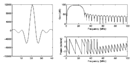
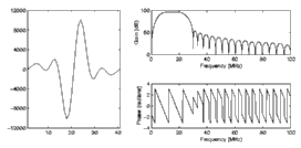
Each matched filter pair must have a gain of exactly 2^16 (i.e. 65536) in the pass band, and the coefficients should be rounded to the nearest integer. The diagrams above show examples of typical filters, in this case 41 coefficients long (so that the delay is exactly 20 samples), with a 10-22MHz pass band at a sampling frequency of 100MHz. The filters can be omitted when recording IQ data, i.e. with a ULA-OP system.
In the case of a ULA-OP system, additional fields are necessary to control the beamforming. An example is given below. Each beamforming scheme requires a name and a reference to one or more .ula files that specify a beamformer setup. This is followed by one or more PROBE_ULAOP_SEQ_BLOCK entries, usually at least one per .ula file. The three numbers for each entry correspond to the 'iItem' (index to the .ula file list), 'iCount' (whether subsequent lines progress laterally) and 'iMerge' (whether beamforming for adjacent lines is merged) parameters of a ULA-OP block sequencer setup. See the ULA-OP documentation for more details on this and how to create custom .ula files.
# options for image type
PROBE_ULAOP_SEQ_NAME   Standard image
PROBE_ULAOP_SEQ_ITEM   image.ula
PROBE_ULAOP_SEQ_BLOCK  0 1 0

PROBE_ULAOP_SEQ_NAME   Steered image
PROBE_ULAOP_SEQ_ITEM   steeredm8deg.ula steeredm4deg.ula image.ula steered4deg.ula steered8deg.ula
PROBE_ULAOP_SEQ_BLOCK  0 1 0
PROBE_ULAOP_SEQ_BLOCK  1 1 0
PROBE_ULAOP_SEQ_BLOCK  2 1 0
PROBE_ULAOP_SEQ_BLOCK  3 1 0
PROBE_ULAOP_SEQ_BLOCK  4 1 0