Difference: GMT_cranioplasty (1 vs. 3)
Revision 3
15 Jul 2014 - gmt11
| Line: 1 to 1 | ||||||||
|---|---|---|---|---|---|---|---|---|
Dr Graham Treece, Department of Engineering | ||||||||
| Line: 20 to 20 | ||||||||
|
| ||||||||
| Changed: | ||||||||
| < < | ||||||||
| > > | ||||||||
| Changed: | ||||||||
| < < | ||||||||
| > > | ||||||||
| Line: 33 to 33 | ||||||||
|
| ||||||||
| Changed: | ||||||||
| < < | ||||||||
| > > | ||||||||
| Changed: | ||||||||
| < < |
| |||||||
| > > |
| |||||||
| Line: 48 to 48 | ||||||||
|
| ||||||||
| Changed: | ||||||||
| < < |
| |||||||
| > > |
| |||||||
| Changed: | ||||||||
| < < |
| |||||||
| > > |
| |||||||
| Line: 64 to 64 | ||||||||
|
| ||||||||
| Changed: | ||||||||
| < < |
| |||||||
| > > |
| |||||||
| Changed: | ||||||||
| < < | ||||||||
| > > | ||||||||
| Line: 76 to 76 | ||||||||
|
| ||||||||
| Changed: | ||||||||
| < < | ||||||||
| > > | ||||||||
| Changed: | ||||||||
| < < |
| |||||||
| > > |
| |||||||
| Line: 89 to 89 | ||||||||
|
| ||||||||
| Changed: | ||||||||
| < < |
| |||||||
| > > |
| |||||||
| Changed: | ||||||||
| < < | ||||||||
| > > | ||||||||
| Line: 102 to 102 | ||||||||
|
| ||||||||
| Changed: | ||||||||
| < < | ||||||||
| > > | ||||||||
| Changed: | ||||||||
| < < |
| |||||||
| > > |
| |||||||
| Line: 115 to 115 | ||||||||
|
| ||||||||
| Changed: | ||||||||
| < < |
| |||||||
| > > |
| |||||||
| Changed: | ||||||||
| < < | ||||||||
| > > | ||||||||
Revision 2
15 Jul 2014 - gmt11
| Line: 1 to 1 | |||||||||||||||||||
|---|---|---|---|---|---|---|---|---|---|---|---|---|---|---|---|---|---|---|---|
Dr Graham Treece, Department of Engineering | |||||||||||||||||||
| Line: 6 to 6 | |||||||||||||||||||
ENGINEERING TRIPOS PART IIA
Module 3G4 - Medical Imaging and 3D Computer Graphics | |||||||||||||||||||
| Changed: | |||||||||||||||||||
| < < |
HTML, Java and GLUT demos | ||||||||||||||||||
| > > |
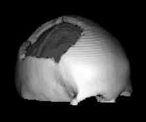
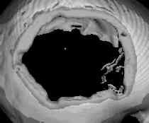
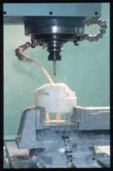
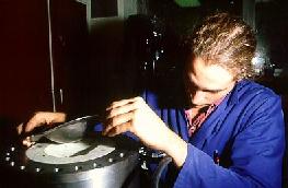
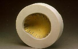
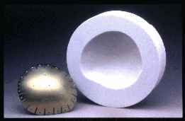
Titanium cranioplasty | ||||||||||||||||||
| Added: | |||||||||||||||||||
| > > |
In this work, medical imaging, computer graphics, surface interpolation and computer-controlled milling are used to create titanium cranial implants at Christchurch Hospital, New Zealand. Researchers: Jonathan Carr, Richard Fright and Rick Beatson, now with Applied Research Associates NZ Ltd .
Author: Jonathan Carr. | ||||||||||||||||||