The hovering helicopter
In this exercise you are going to build a Lego helicopter. Before you get too excited, we should own up and admit that there is not enough lift to get the helicopter off the ground unaided, but by putting the helicopter on a see-saw with a counterweight at the other end, we can measure the lift generated by the blades and do a really interesting experiment in  fluid mechanics. Specifically, we are going to analyse the lift generated by a flat plate. You most probably have come across this effect many times in the past. For example, if you have ever held your hand out of a car window and tilted it, you will have noticed your hand being pushed upwards: a lift force. The magnitude of this force depends on the inclination of your hand, and it is this phenomenon that we are going to study through the Lego helicopter. To achieve this, you will need to build an ingenious mechanism that allows the angle of attack of the helicopter's blades (their pitch) to be varied dynamically while the blades are spinning. You will also need to measure the inclination of the see-saw, and calibrate the relationship between inclination and lift. You can then quantify the lift for a number of pitch angles, and compare your results with some theoretical predictions. You will study the relevant theory later on in the engineering course, for now we provides the basics
  here.
here.
To further appreciate what this exercise involves, start by watching this  movie of the helicopter in action. Take note of the main components: the twin-bladed helicopter at one end of the see-saw, the counterweight at the other, the mechanism to change the pitch angle of the blades, and the Lego light sensor, pointing at a black-grey-white graduated scale, to record the inclination of the see-saw. The generated lift is of the order of a few grams so, sadly, we are a long way from being able to make this helicopter fly unaided!
At each stage of the experiment, the blades' pitch angle is set to a particular value, then the blades are spun up for a predetermined time. The blades are then allowed to come to rest before repeating at the next pitch angle. Throughout the experiment, data is recorded continuously and stored in a results matrix which contains the current time, the position of each of the motors and the light sensor readings. This data is analysed at the end of the experiment, yielding an average light sensor reading for each of the pitch angles. These readings are then converted into lift forces using the results of a calibration procedure that is carried out separately.
Given the complexity of this exercise, we provide you with all the necessary Python code, though you will need to measure some properties of your model and insert the right values into the code at the right places. The software comprises three scripts:  helicopter.py,
 calibrate_pitch.py and
  calibrate_lift.py. The helicopter.py script carries out the entire test procedure. At the top of this file you need to enter the key test parameters, such as the blade pitch angles you wish to study and how long the blades should spin for each test. helicopter.py checks whether the calibration procedures have been performed yet (it looks for their results files) and runs them if not. The first of these procedures, calibrate_pitch.py, establishes an approximate cubic relationship between the position of the motor driving the blade pitch mechanism and the resulting pitch angle. The second, calibrate_lift.py, establishes an approximate quadratic relationship between the light sensor reading and the lift force. calibrate_pitch.py only needs to be run once (unless you change the mechanism), but calibrate_lift.py should be run whenever the ambient light conditions vary.
| Some annotated photographs | |
|---|---|
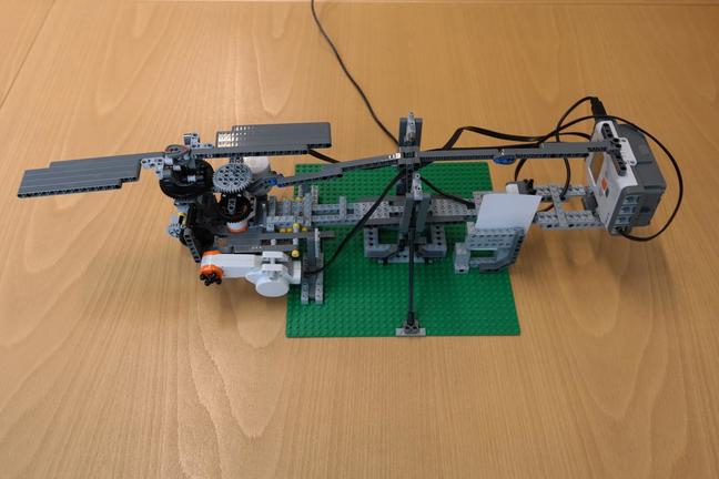 | This photograph shows the full model. The helicopter, on the left of the see-saw, is counterweighted by the NXT brick at the right. The angle of the see-saw is measured by a light sensor, on the right arm, directed at a black-grey-white graduated scale. |
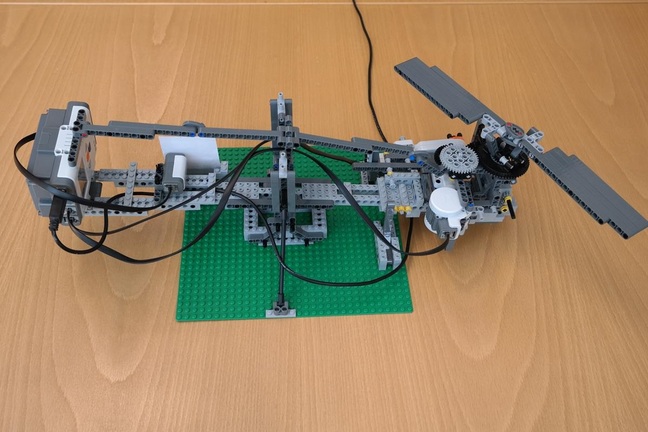 | This photograph shows the reverse view of the model. The see-saw needs to remain reasonably rigid despite the significant torques and vibrations generated by the spinning blades. It is therefore a fairly substantial structure, with light grey bricks along the bottom and dark grey beams providing tension at the top. The support tower is braced from the edges of the baseplate and designed to allow easy adjustment of the pivot axle's height. The pivot needs to be above the see-saw's centre of mass: can you see why? You should experiment with different pivot heights to see what works best. |
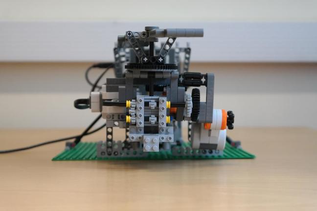
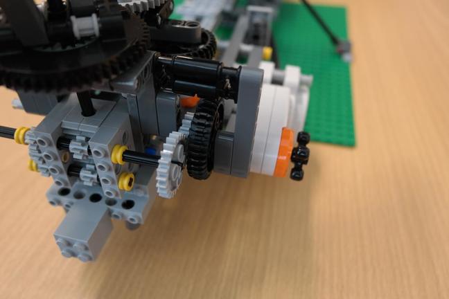
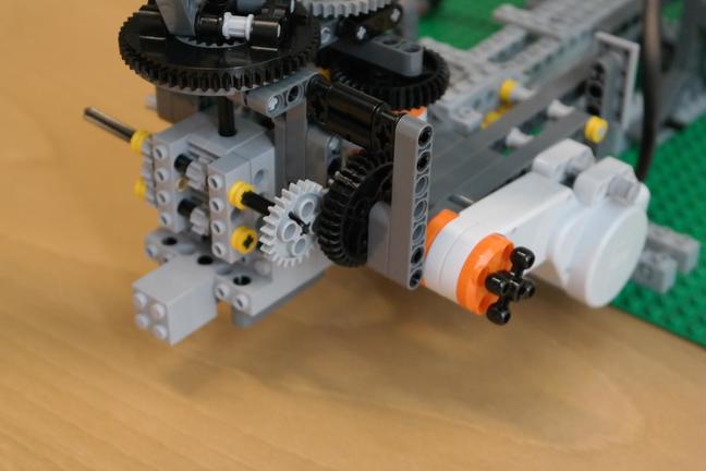
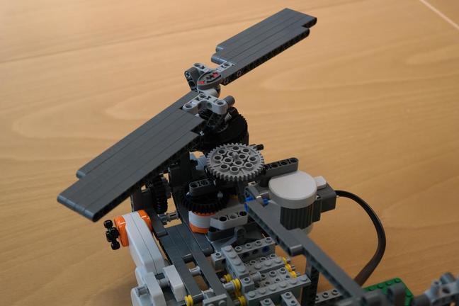
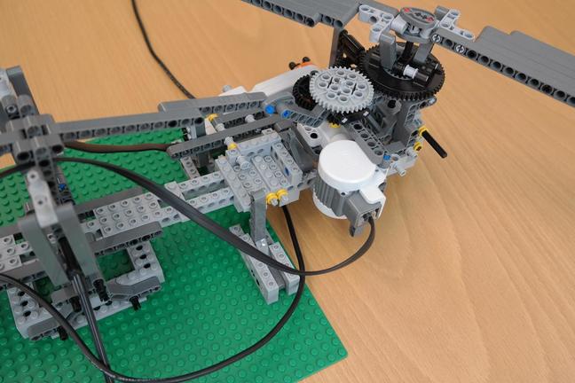
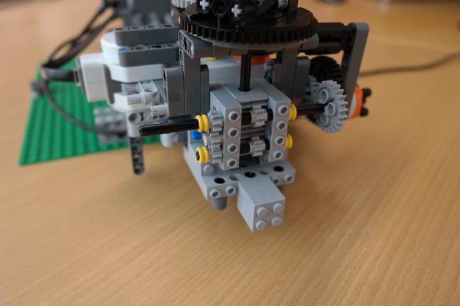
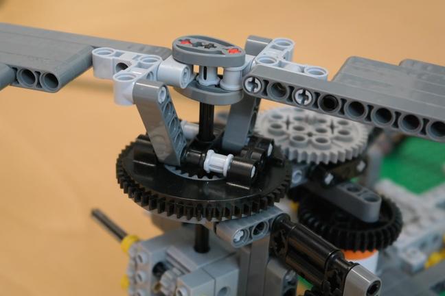
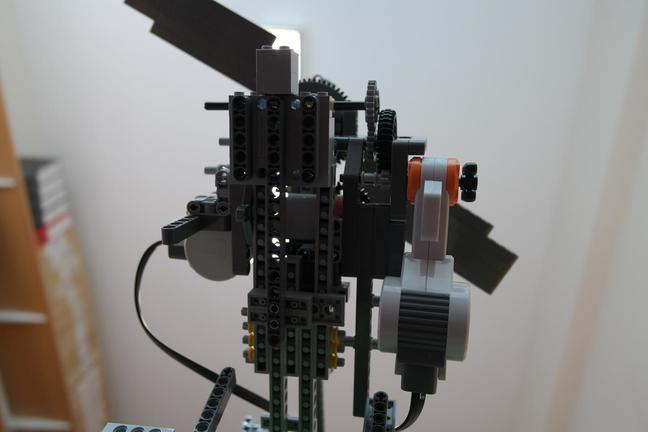
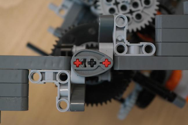
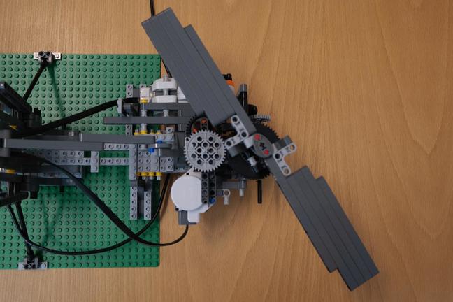
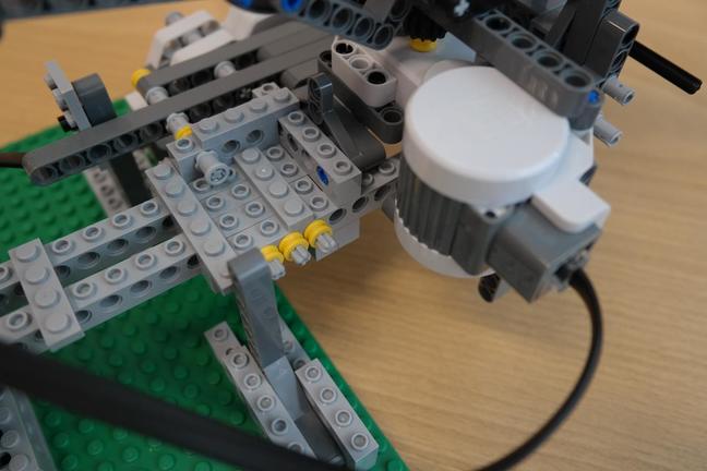
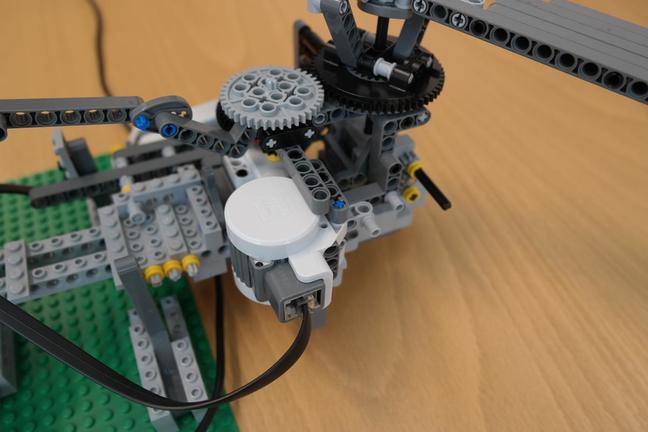
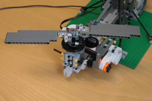 | Perhaps the most difficult mechanism is the one which adjusts the blades' pitch as they rotate. A series of more detailed photographs can be found at the bottom of this page. There are two motors. The one mounted at right angles to the see-saw spins the blades. The rotation of this motor is stepped up through a series of gears to increase the angular velocity of the blades. Think about the optimal gear ratio, bearing in mind that the available torque goes down as the angular velocity goes up. The final gear coupling is to the black turntable onto which the trailing edges of the blades are attached. The leading edges are attached to a central axle that is moved up and down from below: this is how the pitch angle is adjusted. The axle is clamped to a rack and pinion mechanism which is driven by the second motor. The clamp is achieved by a light grey bush sandwiched between two single-hole beams: see the last of the detailed photographs at the bottom of this page. |
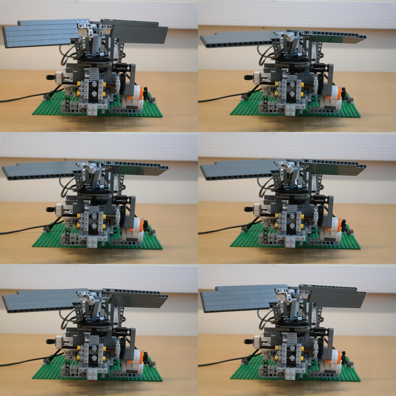 | This animation shows the blade pitch angle adjusting through ten pre-set values. |
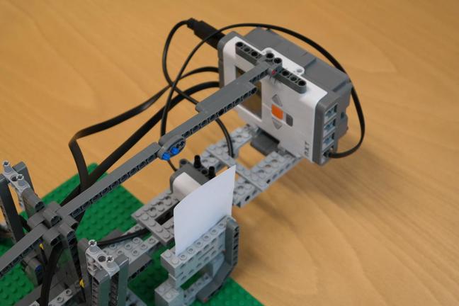 | This photograph shows the other end of the see-saw, with the NXT brick providing most of the counterweight. |
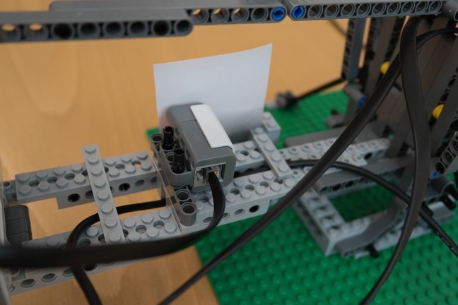 | Here we see the light sensor directed at the black-grey-white graduated scale. As the see-saw tilts, the light sensor finds itself pointing at a different shade of grey and its reading changes accordingly. This is how we measure the see-saw's inclination, though we also need to run a calibration procedure to convert light sensor readings into lift forces. You will need to try different length black-grey-white scales: this  pdf file includes a selection of candidates for you to experiment with. pdf file includes a selection of candidates for you to experiment with. |
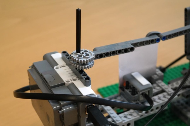 | To calibrate the relationship between the light sensor reading and the lift force, we add weights to the counterweight side of the see-saw, recording the light sensor reading for each incremental weight. For the weights, it is convenient to use a Lego axle onto which can be slotted a variety of gears. You will find the weights of these Lego pieces tabulated  here. Make sure to insert the axle at approximately the same distance from the see-saw pivot as the centre of lift, since calibrate_lift.py does not allow for different lever arm lengths. You will need to re-do this calibration whenever the ambient light conditions change significantly. In contrast, calibrate_pitch.py is a "once only" procedure which finds an approximate cubic relationship between the blade adjustment motor position and the resulting blade angle. You will need to edit the numbers at the top of calibrate_pitch.py to tell the script the blade angles (with respect to horizontal) for a number of different motor positions. If you have a smartphone, look for a handy app that tells you the phone's current inclination. You can then just rest the phone on top of the blades to measure the angles you need. here. Make sure to insert the axle at approximately the same distance from the see-saw pivot as the centre of lift, since calibrate_lift.py does not allow for different lever arm lengths. You will need to re-do this calibration whenever the ambient light conditions change significantly. In contrast, calibrate_pitch.py is a "once only" procedure which finds an approximate cubic relationship between the blade adjustment motor position and the resulting blade angle. You will need to edit the numbers at the top of calibrate_pitch.py to tell the script the blade angles (with respect to horizontal) for a number of different motor positions. If you have a smartphone, look for a handy app that tells you the phone's current inclination. You can then just rest the phone on top of the blades to measure the angles you need. |
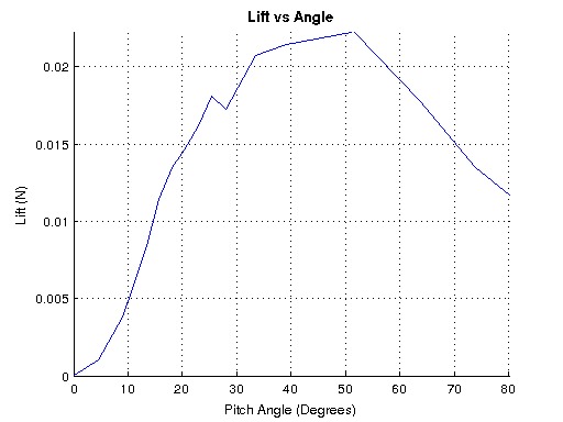 | This graph shows one possible result of running the experiment. We stress it is one possible result, since there are some  subtle effects going on and you will observe different outcomes as you vary the experimental parameters (mainly due to the flow separating at different angles). subtle effects going on and you will observe different outcomes as you vary the experimental parameters (mainly due to the flow separating at different angles). |
Here are some points to bear in mind if you decide to build your own helicopter.
- The current blade adjustment mechanism has a range of approximately -30 to +80 degrees. Can you improve the design to give a longer sweep up to +/-90 degrees? What happens if the blades are tilted to force the helicopter down?
- Why do we let the blades come to a stop between runs? Try changing the code so that the blades run continuously between pitch adjustments. Is there a difference between lift readings when the blade angle is increasing and when it is decreasing? Note that, in general, it takes some time for flow structures to stabilize. There is a nice smartphone app called Wind Tunnel which demonstrates this point very clearly.
- The manual lift calibration is fairly tedious, especially seeing as this has to be repeated whenever the ambient light conditions change. You have a spare motor in the kit, could this be used to automate the calibration routine? The resplendent Roman balance might provide suitable inspiration!
- Flat plates are almost never used in real life to create lift, though they are easy to make out of Lego! Can you design more efficient aerofoil sections, using either Lego or some other material?
-
This device measures lift, but of more interest to aeronautical engineers is a dimensionless coefficient called the
 lift coefficient. To estimate this you will need to find the blade velocity. Of course this varies between the roots and the tips of the blades, but for a decent approximation we can just work with the average velocity half way along the blades (calculate this from the drive motor speed, allowing for the gears between the motor and the blades). Similarly, it is also possible to estimate the
  drag coefficient, though finding the drag force is less straightforward. This
  lovely website looks in detail at the NXT motors: of particular interest is
  this relationship between the rotational speed and torque of an NXT motor. If we assume that all the motor's power is transferred to the blades (is this realistic?), we find that motor_angular_velocity * motor_torque = mean_blade_velocity * mean_drag_force, and we can then go on to estimate the drag coefficient. The lift and drag coefficients are used frequently in aerodynamics to quantify the effectiveness of an aerofoil.
The hovering helicopter was designed and built by Luke Redfern in May 2014.
| Detailed photographs of the pitch adjustment mechanism | |
|---|---|
 |  |
 |  |
 |  |
 |  |
 |  |
 |  |
 |