Main > GMT_VolMorph
Dr Graham Treece, Department of Engineering
VolMorph
For generating and visualising morphing sequences from one polygonal mesh to another. The morphing sequences are generated using maximal disc (or sphere in this case) shape-based interpolation, and triangulated using regularised marching tetrahedra. The whole process is described in detail in a
technical report.
Program overview Obtaining, installing and running VolMorph Output data file formats Command line options Examples Versions
Program overview
VolMorph can be started simply be running the program - there are some
command line options, however these can also be entered at run time, and in any case the default values are usually appropriate. Once started, volmorph displays an empty 'chess board'. Files are loaded by using the 'File' then 'Open' buttons, and entering the 'Source' and 'Target' file names. Once these have been entered, each object is first sampled to three-dimensional arrays where each cell contains the distance to the original polygon. With antialiasing enabled (the default option), this array need not be that large to give a good quality morph - typically only 40 x 40 x 40 is sufficient, though this is dependent on the complexity of the models. Interpolation is then performed on these arrays, and both the original and intermediate surfaces are re-triangulated from this data using regularised marching tetrahedra, so that the morph sequence can be manipulated in real time.
Once the source and target files have been sampled and triangulated, they are both displayed:
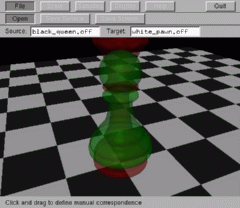
The source surface is shown in translucent red, and the target surface in translucent green. At this point, a set of vectors can be created which link the source surface to the target surface, to provide some indication of how the morph should work. This is done simply by clicking and dragging:
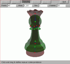
Each vector is shown in blue, with the end points in green or red to indicate which surface they are connected to. This can be more easily seen by turning the display of the base off at this point, and setting the background colour to white, both through the `Display' option.
Manual vector definition is only necessary on quite complex surfaces, since the second step, which is accessed by pressing
<enter>, provides automatic definition of how the surfaces should be connected. In this stage, a set of spheres are estimated for each surface, which approximately represent the surface. These spheres enable a set of vectors to be calculated which indicate how the source and target surfaces should be connected - these vectors are used to guide the creation of the morphing sequence:
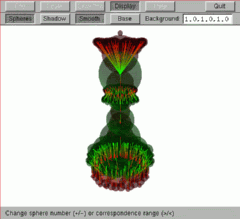
Each vector is shaded from red to green, such that the direction of interpolation is clear. The number of vectors, and the distance over which they can connect the objects, can be controlled by using the '+', '-', '<' or '>' keys - '+' and '-' control the connectivity, whilst '<' and '>' control the number of spheres (and hence also vectors). In addition, individual vectors can be deleted by clicking on them (although they will re-appear if the connectivity is subsequently changed). Note that if the '-q' command line option was used, no vectors will be displayed.
Help on what each key is used for is available at any time by pressing the 'Help' button:
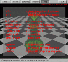
Once the vectors look sensible, the morphing sequence can be initiated by pressing
<enter>. Intermediate surfaces are then interpolated and triangulated, and displayed in the window as they are created. This will take anything from one minute upwards, dependent on the size of the volume, the number of vectors and the number of intermediate frames.
After the intermediate surfaces have been created, the morph from the initial to the final surface is displayed in the window
in real time. This means that the viewpoint can be moved, the lighting altered etc.
while the surface is morphing. The video shown below is an example of this window running at actual speed (although the quality is much better in reality - the video quality has been compromised to make downloading easier):
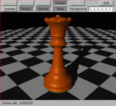
The viewpoint, lighting and model position can all be changed with the mouse. The left and right buttons rotate the scene, and the middle button moves it. If the
<ctrl> key is held down during mouse presses, the action is to the light source, and if the
<shift> key is held down, the action is to the object itself. Note that in all these cases, the movement will continue beyond mouse button release if the mouse was moving during release - i.e. the viewpoint, lighting and object position can be set in motion by use of the mouse.
There are also other options, for instance the shadow can be turned on or off by pressing 'Display' then 'Shadow', and the window can be dumped to a sequence of files (to generate a movie) by using the space bar. In addition, the surfaces which make up the 3D morphing sequence can be written to OOGL or VRML format files while the morph is being created.
The window will return to automatic vector definition mode by pressing
<backspace>, and to the manual vector definition mode by pressing
<backspace> again. Use
<esc>, 'q' or the 'Quit' button to exit.
Obtaining, installing and running VolMorph
VolMorph has been compiled for several environments. If none of the binary executables below are suitable for your platform, please
e-mail me - it may well be possible to compile the software for your platform.
Once you have downloaded the executable, unzip it using
gunzip (except for the Windows executable) - there is only a single file, which does not need a parameter file nor any environment variables. All options are passed to the program as command line parameters.
You will also need either
OpenGL or an equivalent version - the software has been implemented on Linux using
Mesa, for instance. The windows are constructed using
GLUT (the GL Utility Toolkit), so you will need to get a copy of that too. Both Mesa and GLUT are freely available from the internet for a wide variety of platforms. Windows users will need
opengl32.dll,
glu32.dll (which are installed with Windows) as well as
glut32.dll which is available free from
GLUT for Win32.
Since OOGL models are not widely available on the internet, I have also written a utility to convert from 3DS format to OOGL, which can handle colours but not texture maps. This is a single 'C' file, which you are welcome to download and compile, though I would ask that you send me a copy if you manage to make it work better than I have! There is help available by using the '-h' command line option.
Please note that VolMorph is a research tool, and is intended for research / personal use only. Whilst the author would like to think it is fairly well written, it comes with no reliability guarantees - use at your own risk!
Output data file formats
VolMorph can output the morphing sequence in a sequence of files containing the surface triangulation, '
name###.off', or '
name###.wrl' where
### is the frame number and
name is supplied by the user. The former are in OOGL format, which is suitable for use with the
Geomview visualisation package, also available free for most Unix platforms. The latter are in VRML version 1.0, which can be viewed with any VRML viewer. The sphere representations can also be output as '
sphere###.sph' or '
sphere###.wrl'. The order of the vertices in each triangle is consistent, and surface normals are provided for each vertex, so the triangulation can be correctly displayed with either faceted or smooth shading.
Note that these surface are output as the display lists are created - so, for instance, the sphere representations will only be output if (at some point) you view this representation.
It is also possible to dump a sequence of images '
morph###.ppm', or '
morph###.bmp' of the VolMorph window - this feature is toggled on and off using the space bar. These images are in PPM format (except for the Windows version, which write in BMP format), which is just a sequence of bytes, one each for red, green and blue, giving three for each pixel. The file starts with a textual header indicating the type and size, and the source of the data. These files can be used to generate a movie of the morph sequence, for instance using SGI's dmconvert, or the freely available mpeg_encode.
Command line options
All of the options available through the buttons can also be supplied, in any order, as follows:
volmorph [-o filename] [-v] [-f frames] [-p points] [-r resolution] [-c] [-z] [-a distance] [-q] [-h] [initial_file] [final_file]
The initial and final files (in OOGL format) must always be supplied - all other options have default values, as listed below.
Parameter |
Meaning |
Usage |
| |
| |
| |
| |
| |
| |
| |
| |
| |
| |
-a {distance} |
antialias surfaces |
Causes the sampled volumes to be initialised with the actual geometric distance from the input polygons, to a distance of {distance} voxels. Greatly improves the quality of the surfaces. Default is 1.1 - setting {distance} to 0 disables. |
-c |
scale centres |
Causes the initial and final surface to be translated such that the centres are coincident, before interpolating. Default is not to. |
-f {frames} |
interpolated frames |
{frames} defines the number of interpolated surfaces (inclusive) between the inital and final surfaces. Default is 20. |
-h or -? |
Help |
Displays a brief help screen. |
-o {filename} |
output file name |
{filename} defines the root of the output files containing the interpolated surfaces. The default is not to write output files. |
-p {points} |
sampling points |
{points} sets the minimum number of points, in any direction, used to sample the initial and final files. The default is 20. |
-q |
quick interpolation |
Disables the use of vectors in the interpolation and defaults to shape-based interpolation. Default is to use vectors. |
-r {resolution} |
triangulation resolution |
{resolution} defines the resolution of the surface triangles compared to the sampled volume. The default value is 1. Larger values reduce the number of triangles (and the quality of the surface). |
-v |
VRML format |
Output triangulation in VRML rather than OOGL format. |
-z |
scale centres and size |
Causes both the centre and size of the intial and final surfaces to be translated and scaled respectively. This is the default option. |
Examples
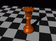
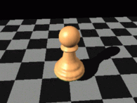
Try running volmorph on the
queen and
pawn models, or a
zipped version of both of them (after downloading and unzipping them), by using the command:
volmorph white_pawn.off black_queen.off
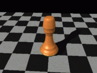
By increasing the connectivity of the vectors, you should be able to obtain a morph like that shown below:
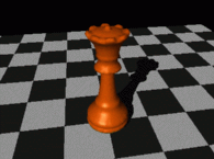
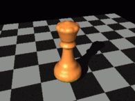
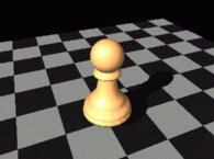
Alternatively, if you turn off the use of vectors, using the '-q' option:
volmorph -q white_pawn.off black_queen.off
This will generate a much poorer morphing sequence:
Versions
Version 2.4b - March 2002
Fixed bug in binary output files for Windows version.
- Added output of spheres in OOGL or VRML format.
Version 2.4 - January 2001
Compiled and tested Linux version for XFree 4.0, using Direct Rendering.
- Added `Cancel' button during creation of the morphed models.
- Can now choose to output screen dumps in either PPM or BMP formats.
Version 2.3 - September 2000
Can now toggle the checkered base on or off, and change the colour of the
background. Also moved some menu options to more sensible positions.
- Changed operation of text boxes within the menus, such that new data is entered if the box is un-selected, not just on pressing .
Version 2.2 - June 2000
Can now generate equation triangulation in VRML version 1.0 as well as
in OOGL.
- Windows version now writes .BMP files as the screen dump rather than .PPM files, since that seemed more useful.
Version 2.1 - April 2000
Major re-write of the command / response structure to allow sensible
compilation under Windows 95/98/NT. Arguments can now be set via a
menu system, and diagnostic output and errors are displayed in the
window.
- Correspondence between surfaces can now be defined manually in 3D, in addition to being refined automatically.
- Various other source only updates to allow compilation under Windows 95/98/NT.
Version 2.0 - February 2000
First public release. Started at version 2.0 to bring it in line
with the equation display software, EqnSurf.


