
Difference: GMTVideos (1 vs. 10)
Revision 10
14 Dec 2023 - gmt11
| Line: 1 to 1 | ||||||||
|---|---|---|---|---|---|---|---|---|
| ||||||||
| Line: 18 to 18 | ||||||||
| Changed: | ||||||||
| < < |
|  | |||||||
| > > |
|  | |||||||
|
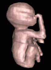
Reconstruction using Shape Based Interpolation. | ||||||||
| Changed: | ||||||||
| < < |
\ |  | |||||||
| > > |
\ |  | |||||||
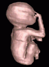
| Reconstruction using Shape Based Interpolation, using centroids to guide the interpolation direction | ||||||||
| Changed: | ||||||||
| < < |
\ |  | |||||||
| > > |
\ |  | |||||||
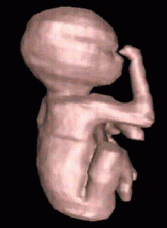
| Reconstruction using an improved version of Disc Guided Interpolation, presented in another technical report. | ||||||||
| Changed: | ||||||||
| < < |
\ |  | |||||||
| > > |
\ |  | |||||||
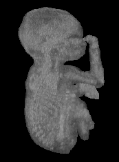
| You can also volume render the actual ultrasound data which the previous surfaces were based on. \ | Part of the portal venous system, reconstructed from six ultrasound B-scans. | ||||||||
| Line: 33 to 33 | ||||||||
|
| | ||||||||
| Changed: | ||||||||
| < < |
\ |  | |||||||
| > > |
\ |  | |||||||
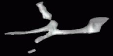
| Reconstruction using Shape Based Interpolation. | ||||||||
| Changed: | ||||||||
| < < |
\ |  | |||||||
| > > |
\ |  | |||||||
|
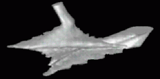
Reconstruction using Shape Based Interpolation, using centroids to guide the interpolation direction.\ | \ | | | ||||||||
| Changed: | ||||||||
| < < |
\ |  | |||||||
| > > |
\ |  | |||||||
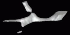
| Reconstruction using Maximal Disc Guided Interpolation, as presented in a technical report. | ||||||||
| Changed: | ||||||||
| < < |
\ |  | |||||||
| > > |
\ |  | |||||||
|
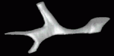
Reconstruction using an improved version of Disc Guided Interpolation, presented in another technical report \ | | ||||||||
| Line: 55 to 55 | ||||||||
|
| | ||||||||
| Changed: | ||||||||
| < < |
\ |  | |||||||
| > > |
\ |  | |||||||
|
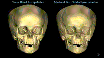
My technique (on the right) compared to Shape Based Interpolation (on the left). Each time the skulls rotate, the number of cross-sections used to define the surface is reduced, starting at 145 and finishing at 20. The skull on the left clearly degrades more quickly than that on the right. \ | | ||||||||
| Line: 63 to 63 | ||||||||
|
\ |
| | ||||||||
| Changed: | ||||||||
| < < |
\ |  | |||||||
| > > |
\ |  | |||||||
|
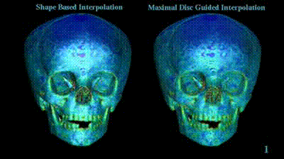
The same as above, save that the surface has been colour coded with an estimate of surface curvature (deep blue for low curvature, to red for high curvature). This accentuates the areas of poor surface interpolation. \ | | ||||||||
| Line: 88 to 88 | ||||||||
|
\ |
| | ||||||||
| Changed: | ||||||||
| < < |
\ |  | |||||||
| > > |
\ |  | |||||||
|
| ||||||||
| Changed: | ||||||||
| < < |
\ |  | |||||||
| > > |
\ |  | |||||||
|
\ | \ | | | ||||||||
| Changed: | ||||||||
| < < |
\ |  | |||||||
| > > |
\ |  | |||||||
|
| ||||||||
| Changed: | ||||||||
| < < |
\ |  | |||||||
| > > |
\ |  | |||||||
|
\ | \ | | | ||||||||
| Changed: | ||||||||
| < < |
\ |  | |||||||
| > > |
\ |  | |||||||
|
| ||||||||
| Changed: | ||||||||
| < < |
\ |  | |||||||
| > > |
\ |  | |||||||
|
\ | \ | | | ||||||||
| Changed: | ||||||||
| < < |
\ |  | |||||||
| > > |
\ |  | |||||||
|
| ||||||||
| Changed: | ||||||||
| < < |
\ |  | |||||||
| > > |
\ |  | |||||||
|
\ | \ | | | ||||||||
| Changed: | ||||||||
| < < |
\ |  | |||||||
| > > |
\ |  | |||||||
|
| ||||||||
| Changed: | ||||||||
| < < |
\ |  | |||||||
| > > |
\ |  | |||||||
|
\ | \ | | | ||||||||
| Changed: | ||||||||
| < < |
\ |  | |||||||
| > > |
\ |  | |||||||
|
| ||||||||
| Changed: | ||||||||
| < < |
\ |  | |||||||
| > > |
\ |  | |||||||
|
\ | | ||||||||
| Line: 143 to 143 | ||||||||
| ||||||||
Revision 9
08 Feb 2021 - gmt11
| Line: 1 to 1 | ||||||||
|---|---|---|---|---|---|---|---|---|
| ||||||||
| Line: 18 to 18 | ||||||||
| Changed: | ||||||||
| < < |
|  | |||||||
| > > |
|  | |||||||
|
Reconstruction using Shape Based Interpolation. | ||||||||
| Changed: | ||||||||
| < < |
\ |  | |||||||
| > > |
\ |  | |||||||
| Reconstruction using Shape Based Interpolation, using centroids to guide the interpolation direction | ||||||||
| Changed: | ||||||||
| < < |
\ |  | |||||||
| > > |
\ |  | |||||||
| Reconstruction using an improved version of Disc Guided Interpolation, presented in another technical report. | ||||||||
| Changed: | ||||||||
| < < |
\ |  | |||||||
| > > |
\ |  | |||||||
| You can also volume render the actual ultrasound data which the previous surfaces were based on. \ | | ||||||||
| Deleted: | ||||||||
| < < | ||||||||
| Part of the portal venous system, reconstructed from six ultrasound B-scans. | ||||||||
| Line: 34 to 33 | ||||||||
|
| | ||||||||
| Changed: | ||||||||
| < < |
\ |  | |||||||
| > > |
\ |  | |||||||
| Reconstruction using Shape Based Interpolation. | ||||||||
| Changed: | ||||||||
| < < |
\ |  | |||||||
| > > |
\ |  | |||||||
|
Reconstruction using Shape Based Interpolation, using centroids to guide the interpolation direction.\ | \ | | | ||||||||
| Changed: | ||||||||
| < < |
\ |  | |||||||
| > > |
\ |  | |||||||
| Reconstruction using Maximal Disc Guided Interpolation, as presented in a technical report. | ||||||||
| Changed: | ||||||||
| < < |
\ |  | |||||||
| > > |
\ |  | |||||||
|
Reconstruction using an improved version of Disc Guided Interpolation, presented in another technical report \ | | ||||||||
| Line: 57 to 55 | ||||||||
|
| | ||||||||
| Changed: | ||||||||
| < < |
\ |  | |||||||
| > > |
\ |  | |||||||
|
My technique (on the right) compared to Shape Based Interpolation (on the left). Each time the skulls rotate, the number of cross-sections used to define the surface is reduced, starting at 145 and finishing at 20. The skull on the left clearly degrades more quickly than that on the right. \ | | ||||||||
| Line: 65 to 63 | ||||||||
|
\ |
| | ||||||||
| Changed: | ||||||||
| < < |
\ |  | |||||||
| > > |
\ |  | |||||||
|
The same as above, save that the surface has been colour coded with an estimate of surface curvature (deep blue for low curvature, to red for high curvature). This accentuates the areas of poor surface interpolation. \ | | ||||||||
| Line: 73 to 71 | ||||||||
Morphing Sequences | ||||||||
| Changed: | ||||||||
| < < | You can also apply essentially the same algorithm used to interpolate the cross-sections above to form surfaces to the interpolation of surfaces themselves. This can be used to generate a sequence of interpolated surfaces in between an initial and a final surface - i.e. a three-dimensional morph. Unlike conventional 2D image morphing, 3D morphing enables you to change the camera viewpoint and lighting parameters during the morphing sequence. Here are a couple of examples, both generated using software which is available to download, and described in a technical report. | |||||||
| > > | You can also apply essentially the same algorithm used to interpolate the cross-sections above to form surfaces to the interpolation of surfaces themselves. This can be used to generate a sequence of interpolated surfaces in between an initial and a final surface - i.e. a three-dimensional morph. Unlike conventional 2D image morphing, 3D morphing enables you to change the camera viewpoint and lighting parameters during the morphing sequence. Here are a couple of examples, both generated using software which is available to download, and described in a technical report. | |||||||
| Note that all these images and videos have been generated at very low resolutions in order to make them possible to download! The real thing is of much higher quality. | ||||||||
| Line: 90 to 88 | ||||||||
|
\ |
| | ||||||||
| Changed: | ||||||||
| < < |
\ |  | |||||||
| > > |
\ |  | |||||||
|
| ||||||||
| Changed: | ||||||||
| < < |
\ |  | |||||||
| > > |
\ |  | |||||||
|
\ | \ | | | ||||||||
| Changed: | ||||||||
| < < |
\ |  | |||||||
| > > |
\ |  | |||||||
|
| ||||||||
| Changed: | ||||||||
| < < |
\ |  | |||||||
| > > |
\ |  | |||||||
|
\ | \ | | | ||||||||
| Changed: | ||||||||
| < < |
\ |  | |||||||
| > > |
\ |  | |||||||
|
| ||||||||
| Changed: | ||||||||
| < < |
\ |  | |||||||
| > > |
\ |  | |||||||
|
\ | \ | | | ||||||||
| Changed: | ||||||||
| < < |
\ |  | |||||||
| > > |
\ |  | |||||||
|
| ||||||||
| Changed: | ||||||||
| < < |
\ |  | |||||||
| > > |
\ |  | |||||||
|
\ | \ | | | ||||||||
| Changed: | ||||||||
| < < |
\ |  | |||||||
| > > |
\ |  | |||||||
|
| ||||||||
| Changed: | ||||||||
| < < |
\ |  | |||||||
| > > |
\ |  | |||||||
|
\ | \ | | | ||||||||
| Changed: | ||||||||
| < < |
\ |  | |||||||
| > > |
\ |  | |||||||
|
| ||||||||
| Changed: | ||||||||
| < < |
\ |  | |||||||
| > > |
\ |  | |||||||
|
\ | | ||||||||
Revision 8
11 Sep 2020 - gmt11
| Line: 1 to 1 | ||||||||
|---|---|---|---|---|---|---|---|---|
| ||||||||
| Changed: | ||||||||
| < < |
Dr Graham Treece, Department of Engineering | |||||||
| > > | Dr Graham Treece, Department of Engineering | |||||||
Videos | ||||||||
| Changed: | ||||||||
| < < | Here are some videos of surface reconstructions and morphing sequences ... | |||||||
| > > | Here are some very old videos of surface reconstructions and morphing sequences ... | |||||||
In vivo surface reconstruction | ||||||||
| Line: 19 to 18 | ||||||||
| Changed: | ||||||||
| < < |
|  | |||||||
| > > |
|  | |||||||
|
Reconstruction using Shape Based Interpolation. | ||||||||
| Changed: | ||||||||
| < < |
|  | |||||||
| > > |
\ |  | |||||||
| Reconstruction using Shape Based Interpolation, using centroids to guide the interpolation direction | ||||||||
| Changed: | ||||||||
| < < |
|  | |||||||
| > > |
\ |  | |||||||
| Reconstruction using an improved version of Disc Guided Interpolation, presented in another technical report. | ||||||||
| Changed: | ||||||||
| < < |
|  | |||||||
| > > |
\ |  | |||||||
| You can also volume render the actual ultrasound data which the previous surfaces were based on. | ||||||||
| Changed: | ||||||||
| < < | | | |||||||
| > > | \ | | |||||||
| Part of the portal venous system, reconstructed from six ultrasound B-scans. | ||||||||
| Line: 40 to 34 | ||||||||
|
| | ||||||||
| Changed: | ||||||||
| < < |
|  | |||||||
| > > |
\ |  | |||||||
| Reconstruction using Shape Based Interpolation. | ||||||||
| Changed: | ||||||||
| < < |
|  | |||||||
| > > |
\ |  | |||||||
| Reconstruction using Shape Based Interpolation, using centroids to guide the interpolation direction. | ||||||||
| Changed: | ||||||||
| < < |
| | |||||||
| > > |
\ | | |||||||
|
| ||||||||
| Changed: | ||||||||
| < < | | | |||||||
| > > | \ | | |||||||
|
| | ||||||||
| Changed: | ||||||||
| < < |
|  | |||||||
| > > |
\ |  | |||||||
| Reconstruction using Maximal Disc Guided Interpolation, as presented in a technical report. | ||||||||
| Changed: | ||||||||
| < < |
|  | |||||||
| > > |
\ |  | |||||||
| Reconstruction using an improved version of Disc Guided Interpolation, presented in another technical report | ||||||||
| Changed: | ||||||||
| < < |
| | |||||||
| > > |
\ | | |||||||
|
| ||||||||
| Changed: | ||||||||
| < < | | | |||||||
| > > | \ | | |||||||
| A child's skull, reconstructed from a varying number of Computed Tomography images. | ||||||||
| Line: 72 to 57 | ||||||||
|
| | ||||||||
| Changed: | ||||||||
| < < |
|  | |||||||
| > > |
\ |  | |||||||
| My technique (on the right) compared to Shape Based Interpolation (on the left). Each time the skulls rotate, the number of cross-sections used to define the surface is reduced, starting at 145 and finishing at 20. The skull on the left clearly degrades more quickly than that on the right. | ||||||||
| Changed: | ||||||||
| < < |
| | |||||||
| > > |
\ | | |||||||
|
| ||||||||
| Changed: | ||||||||
| < < | | | |||||||
| > > | \ | | |||||||
|
| | ||||||||
| Changed: | ||||||||
| < < |
|  | |||||||
| > > |
\ |  | |||||||
| The same as above, save that the surface has been colour coded with an estimate of surface curvature (deep blue for low curvature, to red for high curvature). This accentuates the areas of poor surface interpolation. | ||||||||
| Changed: | ||||||||
| < < |
| | |||||||
| > > |
\ | | |||||||
|
| ||||||||
| Changed: | ||||||||
| < < | | | |||||||
| > > | \ | | |||||||
Morphing Sequences | ||||||||
| Changed: | ||||||||
| < < | You can also apply essentially the same algorithm used to interpolate the cross-sections above to form surfaces to the interpolation of surfaces themselves. This can be used to generate a sequence of interpolated surfaces in between an initial and a final surface - i.e. a three-dimensional morph. Unlike conventional 2D image morphing, 3D morphing enables you to change the camera viewpoint and lighting parameters during the morphing sequence. Here are a couple of examples, both generated using software which is available to download, and described in a technical report. | |||||||
| > > | You can also apply essentially the same algorithm used to interpolate the cross-sections above to form surfaces to the interpolation of surfaces themselves. This can be used to generate a sequence of interpolated surfaces in between an initial and a final surface - i.e. a three-dimensional morph. Unlike conventional 2D image morphing, 3D morphing enables you to change the camera viewpoint and lighting parameters during the morphing sequence. Here are a couple of examples, both generated using software which is available to download, and described in a technical report. | |||||||
| Note that all these images and videos have been generated at very low resolutions in order to make them possible to download! The real thing is of much higher quality. | ||||||||
| Line: 103 to 81 | ||||||||
|
| | ||||||||
| Changed: | ||||||||
| < < | | Source model (click on image for larger version). | |||||||
| > > | \ | Source model (click on image for larger version). | |||||||
|
| ||||||||
| Changed: | ||||||||
| < < | | Target model (click on image for mpeg video). | |||||||
| > > | \ | Target model (click on image for mpeg video). | |||||||
|
| ||||||||
| Changed: | ||||||||
| < < |
| | |||||||
| > > |
\ | | |||||||
|
| ||||||||
| Changed: | ||||||||
| < < | | | |||||||
| > > | \ | | |||||||
|
| | ||||||||
| Changed: | ||||||||
| < < |
|  | |||||||
| > > |
\ |  | |||||||
|
| ||||||||
| Changed: | ||||||||
| < < |
|  | |||||||
| > > |
\ |  | |||||||
|
| ||||||||
| Changed: | ||||||||
| < < |
| | |||||||
| > > |
\ | | |||||||
|
| ||||||||
| Changed: | ||||||||
| < < | | | |||||||
| > > | \ | | |||||||
|
| | ||||||||
| Changed: | ||||||||
| < < |
|  | |||||||
| > > |
\ |  | |||||||
|
| ||||||||
| Changed: | ||||||||
| < < |
|  | |||||||
| > > |
\ |  | |||||||
|
| ||||||||
| Changed: | ||||||||
| < < |
| | |||||||
| > > |
\ | | |||||||
|
| ||||||||
| Changed: | ||||||||
| < < | | | |||||||
| > > | \ | | |||||||
|
| | ||||||||
| Changed: | ||||||||
| < < |
|  | |||||||
| > > |
\ |  | |||||||
|
| ||||||||
| Changed: | ||||||||
| < < |
|  | |||||||
| > > |
\ |  | |||||||
|
| ||||||||
| Changed: | ||||||||
| < < |
| | |||||||
| > > |
\ | | |||||||
|
| ||||||||
| Changed: | ||||||||
| < < | | | |||||||
| > > | \ | | |||||||
|
| | ||||||||
| Changed: | ||||||||
| < < |
|  | |||||||
| > > |
\ |  | |||||||
|
| ||||||||
| Changed: | ||||||||
| < < |
|  | |||||||
| > > |
\ |  | |||||||
|
| ||||||||
| Changed: | ||||||||
| < < |
| | |||||||
| > > |
\ | | |||||||
|
| ||||||||
| Changed: | ||||||||
| < < | | | |||||||
| > > | \ | | |||||||
|
| | ||||||||
| Changed: | ||||||||
| < < |
|  | |||||||
| > > |
\ |  | |||||||
|
| ||||||||
| Changed: | ||||||||
| < < |
|  | |||||||
| > > |
\ |  | |||||||
|
| ||||||||
| Changed: | ||||||||
| < < |
| | |||||||
| > > |
\ | | |||||||
|
| ||||||||
| Changed: | ||||||||
| < < | | | |||||||
| > > | \ | | |||||||
|
| | ||||||||
| Changed: | ||||||||
| < < |
|  | |||||||
| > > |
\ |  | |||||||
|
| ||||||||
| Changed: | ||||||||
| < < |
|  | |||||||
| > > |
\ |  | |||||||
|
| ||||||||
| Changed: | ||||||||
| < < |
| | |||||||
| > > |
\ | | |||||||
|
| ||||||||
| Changed: | ||||||||
| < < | | | |||||||
| > > | \ | | |||||||